System and method for processing images using centralized image correction data

a technology of image correction and image sensor, applied in the field of system and method for processing images using centralized image correction data, can solve the problems of photo-detectors accumulating charge, ccd and cmos image sensors often contain defects that produce undesirable noise in images, and significant noise sources, etc., and achieve cost-effective effects

Inactive Publication Date: 2006-11-30
APTINA IMAGING CORP
View PDF8 Cites 76 Cited by
  • Summary
  • Abstract
  • Description
  • Claims
  • Application Information

AI Technical Summary

Benefits of technology

[0008] Embodiments of the present invention provide a cost-effective image processing system for processing images captured by various imaging devices. The image processing system includes a centralized database for storing image correction data for each of the imaging devices. The image processing system further includes an image processor for receiving original ima

Problems solved by technology

Despite advances in the manufacturing process, both CCD and CMOS image sensors often contain defects that produce undesirable noise in the image.
For example, one significant source of noise in an image is known as “dark current noise.” Dark current noise is a fixed pattern noise that results from manufacturing defects in the photo-detectors.
The defects cause the photo-detectors to accumulate charge even in the absence of light.
Typically, the dark current in an image sensor creates an undesirable “dark” image that overlays the illuminated image.
Another source of noise that is common in digital image sensors that utilize a color filter array (CFA) is color aliasing or color distortion.
However, when the CFA itself contains defects that distort the color sensed at each pixel location, color aliasing artifacts in the image are prevalent even with various color aliasing removal techniques.
For example, if the specifications of a color filter drift either in thickness or in spectral shape (absorbance vs. wavelength) from the manufacturing specifications, the color correction coefficients used in converting the R, G and B sensor values into the demosaiced image values may be incorrect.
In addition t

Method used


Image

  • System and method for processing images using centralized image correction data
  • System and method for processing images using centralized image correction data
  • System and method for processing images using centralized image correction data

Examples


Embodiment Construction

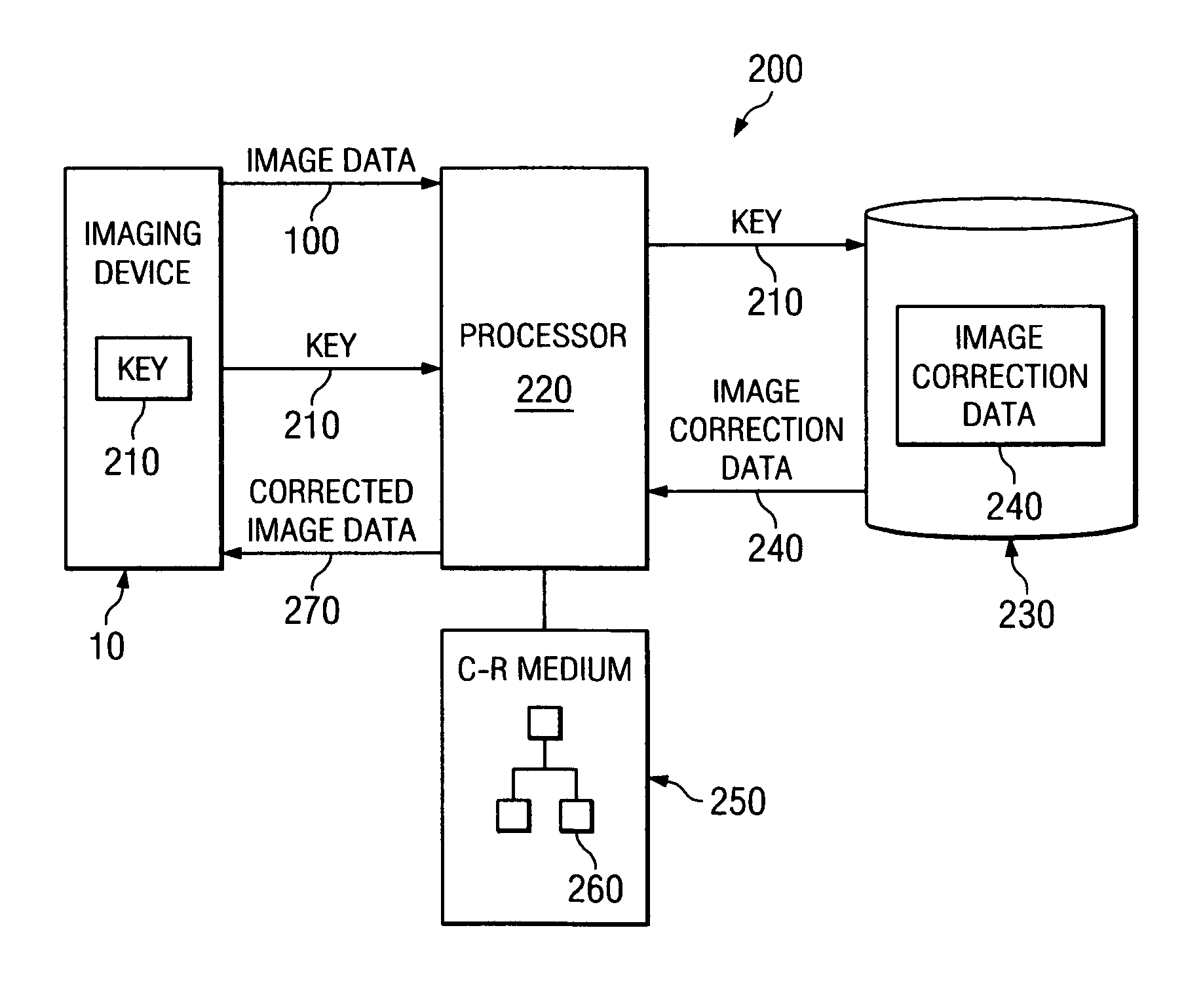
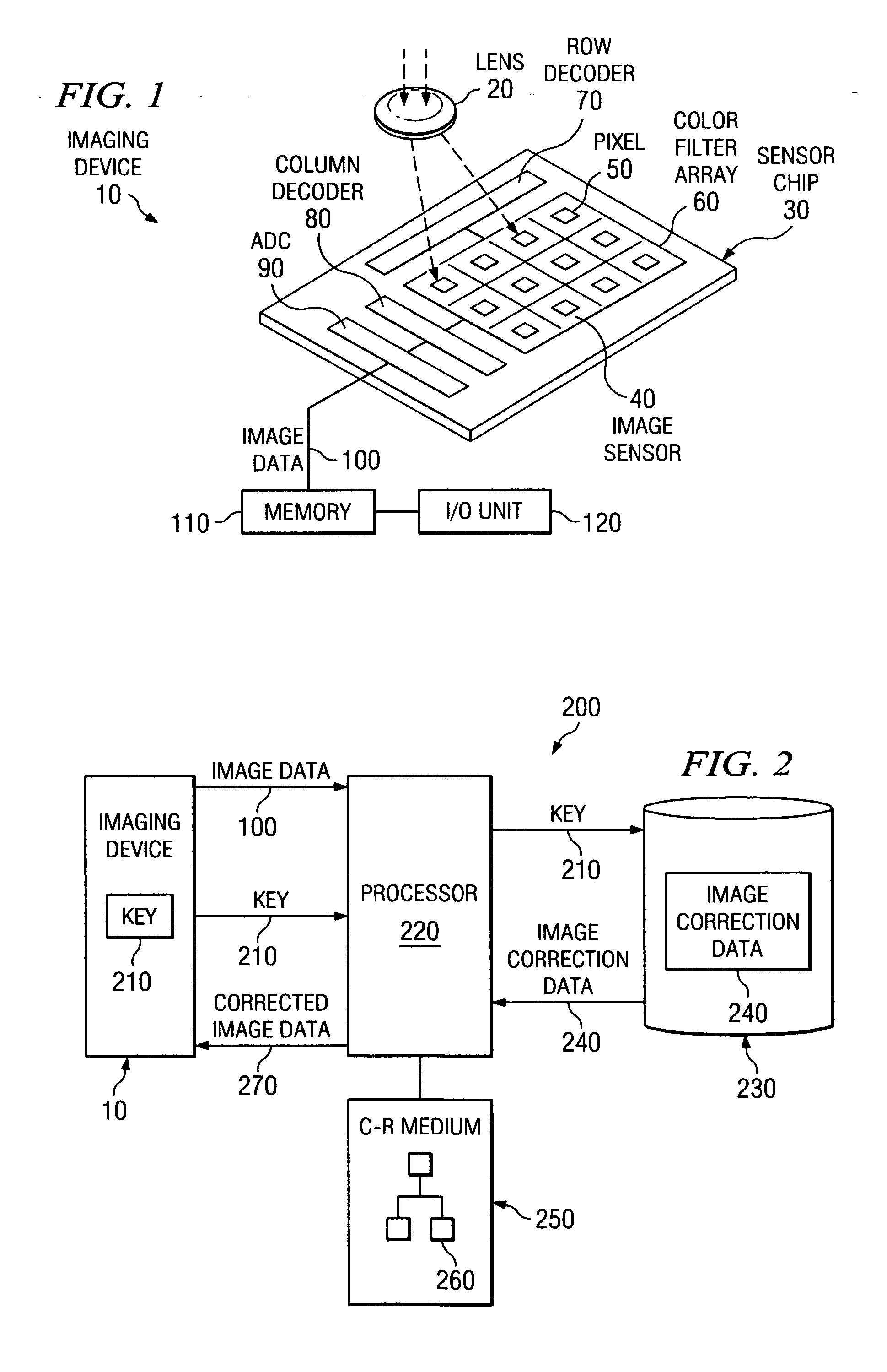
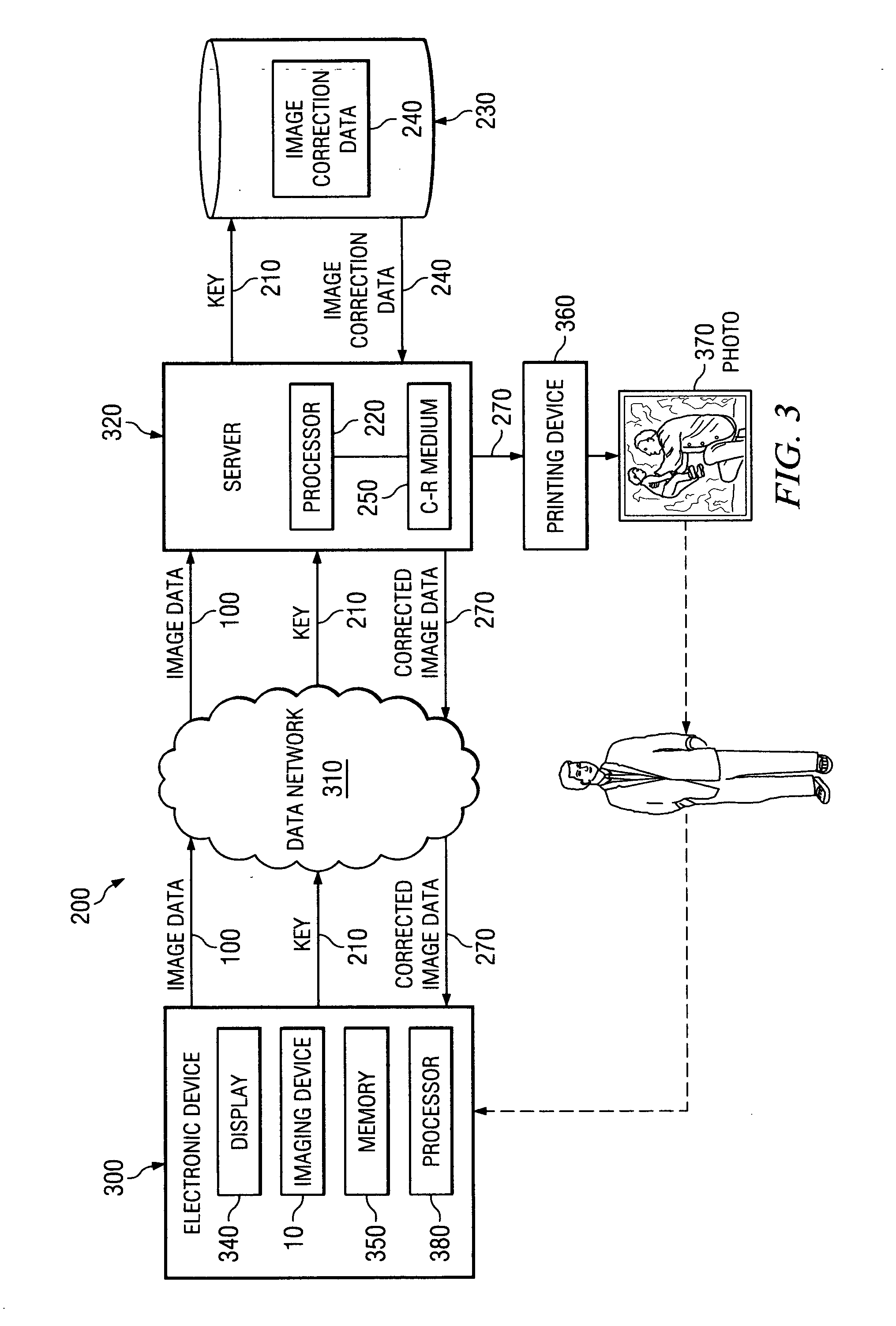
[0017]FIG. 1 illustrates an exemplary imaging device 10 for use in capturing an image that can be corrected using centralized image correction data, in accordance with embodiments of the present invention. The imaging device 10 can be incorporated into any electronic device, such as a cell phone, PDA, digital camera, video camera, medical imaging device or other similar electronic device. In addition, the imaging device 10 is capable of connecting to a computing device, such as a processing device, a personal computer, server, web server, or other similar computing device, to access the centralized image correction data to correct the captured image.

[0018] The imaging device 10 includes a lens 20 and an image sensor chip 30, such as a CMOS sensor chip or a CCD sensor chip. The sensor chip 300 includes a digital image sensor 40 having an array of photo-detectors 50, each corresponding to a pixel of an image projected thereon. The digital image sensor 40 is covered by a color filter ...


PUM


Abstract

An image processing system uses centralized image correction data to process digital images. The image processing system includes a centralized database for storing image correction data for imaging devices. An image processor that receives image data representing an image captured by one of the imaging devices accesses the centralized database with a key associated with the imaging device to retrieve the image correction data for the imaging device. The image processor processes the image data using the retrieved image correction data to correct the image data by reducing various noise components in the image.

Description

BACKGROUND OF THE INVENTION [0001] Digital image sensors are predominantly of two types: CCD (Charge Coupled Devices) and CMOS-APS (Complementary Metal Oxide Semiconductor—Active Pixel Sensors). Both types of sensors typically contain an array of photo-detectors, arranged in a pattern, that generate electrical charge in response to light. Each photo-detector corresponds to a pixel of an image and measures the intensity of light of the pixel within one or ranges of wavelengths, corresponding to one or more perceived colors. [0002] Despite advances in the manufacturing process, both CCD and CMOS image sensors often contain defects that produce undesirable noise in the image. For example, one significant source of noise in an image is known as “dark current noise.” Dark current noise is a fixed pattern noise that results from manufacturing defects in the photo-detectors. The defects cause the photo-detectors to accumulate charge even in the absence of light. Typically, the dark current...

Claims


Application Information

Patent Timeline
IPC IPC(8): G06F3/12G03F3/08H04N5/361H04N5/367
CPCH04N1/00244H04N5/232H04N5/23222H04N5/361H04N2201/3256H04N9/74H04N2201/3205H04N2201/3242H04N5/367H04N23/661H04N23/64H04N25/68H04N25/63H04N1/603H04N25/67H04N5/21H04N23/00H04N23/12
Inventor VOOK, DIETRICH WERNERWENSTRAND, JOHN STEWART
Owner APTINA IMAGING CORP
Why Eureka
Try Eureka