Automatic bit rate control circuit
a bit rate control and automatic technology, applied in the field of preamplifier control, can solve the problems of reduced trans-impedance gain, increased received power, and inability to accurately discriminate bit-rate in the conventional bit-rate discrimination circuit described abov
- Summary
- Abstract
- Description
- Claims
- Application Information
AI Technical Summary
Benefits of technology
Problems solved by technology
Method used
Image

Examples
first embodiment
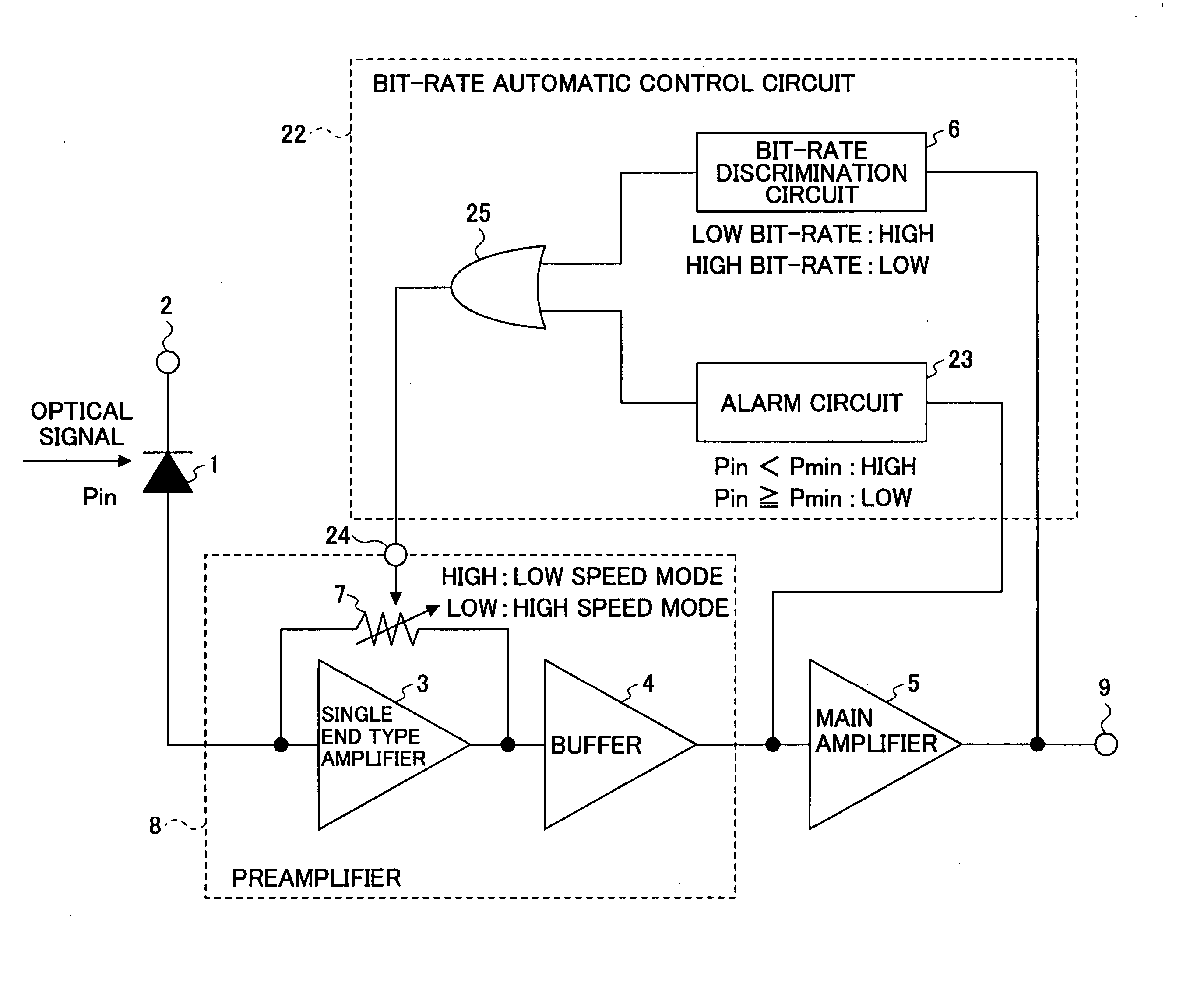
[0110]FIG. 10 is a block diagram showing a multi bit-rate discrimination circuit according to a first embodiment of the present invention. In FIG. 10, the same reference symbol as used in FIG. 3 denotes a similar component. A reference numeral 22 denotes a bit-rate automatic control circuit; 23 denotes an alarm circuit; 24 denotes a control terminal for switching feedback resistors; and 25 denotes a dual input OR circuit.
[0111]FIG. 11 shows an example of the alarm circuit 23. In FIG. 11, the same reference symbol as used in FIG. 4 denotes a similar component. A reference numeral 26 denotes a multiplier; 27 denotes an integrator; 28 denotes a comparator; 29 denotes an inverted output terminal of the comparator 28; and 30 denotes an input terminal for a reference voltage (Vref).
[0112] The alarm circuit 23 is a circuit for converting the amplitude of an input signal into the voltage of an output signal. The input signal is fed to the multiplier 26, and is integrated by the integrator...
second embodiment
[0131] Referring to FIGS. 20 and 21, the second embodiment of the present invention is described below.
[0132]FIG. 20 is a block diagram showing a multi bit-rate receiver according to the second embodiment of the present invention. In FIG. 20, the same reference symbol as used in FIG. 10 denotes a similar component. Reference numerals 44 and 45 denote a branch or distribution circuit; 46 denotes a feedback resistor; 47 denotes a voltage controlled switch or a voltage controlled switch element. “N” sets of the bit-rate discrimination circuits 6, the control terminals for switching feedback resistor 24, the OR circuits 25, the feedback resistors 46, the voltage controlled switches or voltage controlled switch elements 47 are used in parallel, each set being identified by an index number in parentheses. Because N bit-rate discrimination circuits 6(1)-6(N) are used in parallel, and N sets of a feedback resistor 46 for changing the feedback resistor of the preamplifier 8 and a voltage co...
PUM
 Abstract
Description
Claims
Application Information