Turbine airfoil trailing edge cooling system with segmented impingement ribs

Inactive Publication Date: 2006-11-30
SIEMENS ENERGY INC
View PDF16 Cites 13 Cited by
  • Summary
  • Abstract
  • Description
  • Claims
  • Application Information

AI Technical Summary

Benefits of technology

[0005] This invention relates to a turbine airfoil cooling system including a trailing edge cooling channel with at least one segmented rib having a plurality of impingement orifices. The segmented rib increases the efficiency of the cooling system in the airfoil and increases the strength of the airfoil in the trailing edge region. The trailing edge cooling channel may be configured su

Problems solved by technology

In addition, turbine blades often contain cooling systems for prolonging the life of the blades and reducing the likelihood of failure as a result of excessive temperatures.
However, centrifugal forces and air flow at boundary layers often prevent some areas of the turbin

Method used


Image

  • Turbine airfoil trailing edge cooling system with segmented impingement ribs
  • Turbine airfoil trailing edge cooling system with segmented impingement ribs
  • Turbine airfoil trailing edge cooling system with segmented impingement ribs

Examples


Embodiment Construction

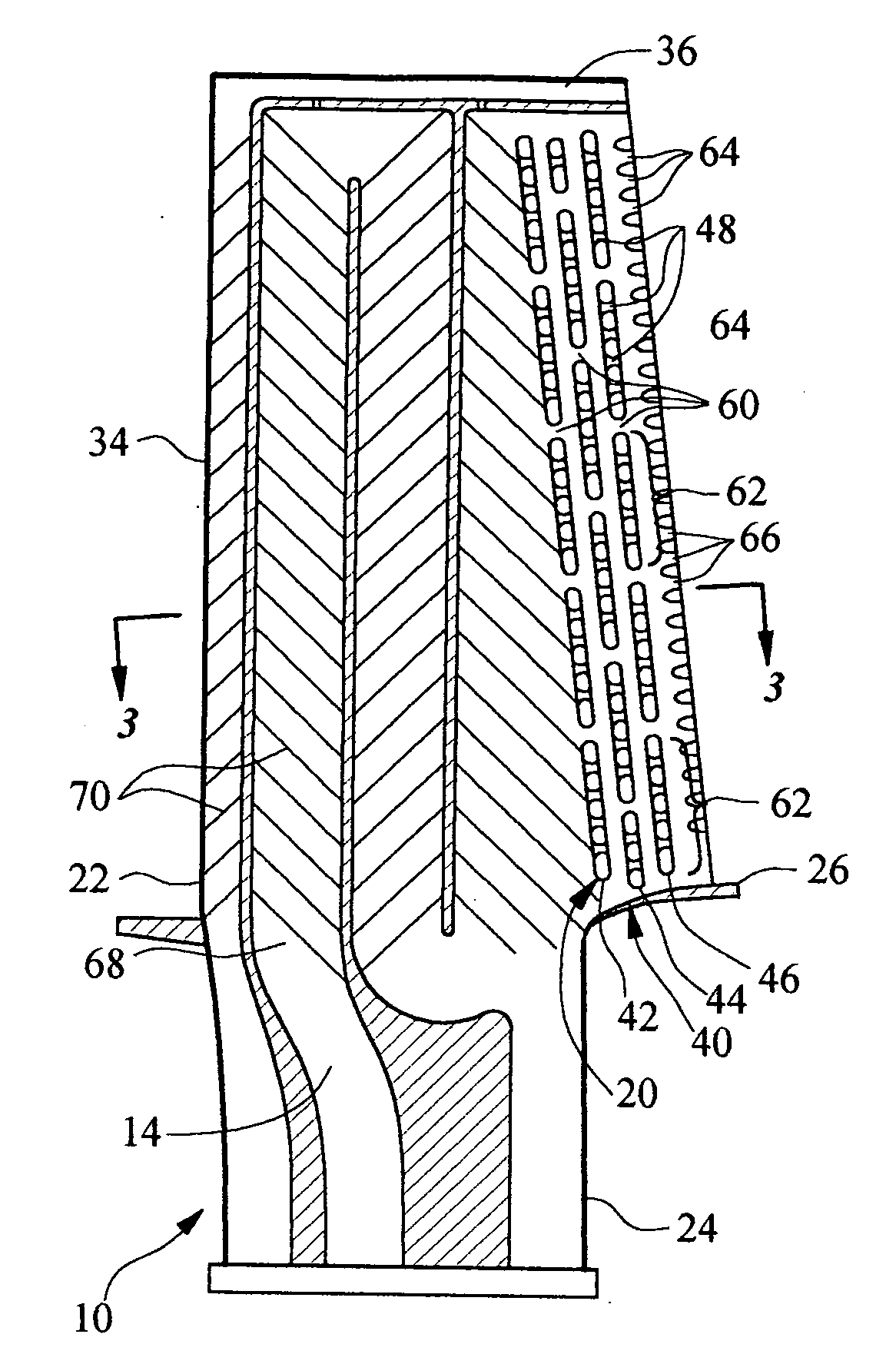
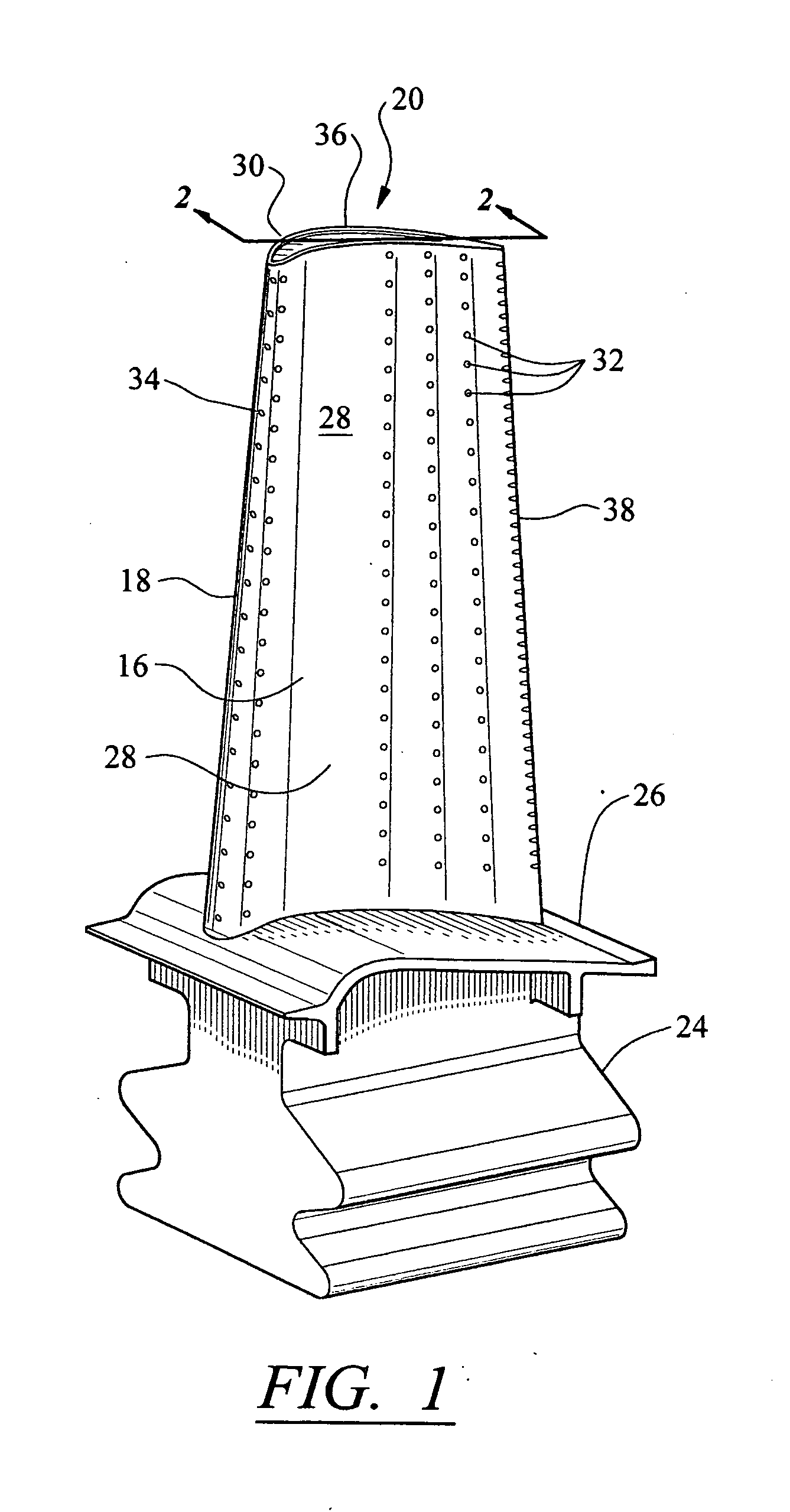
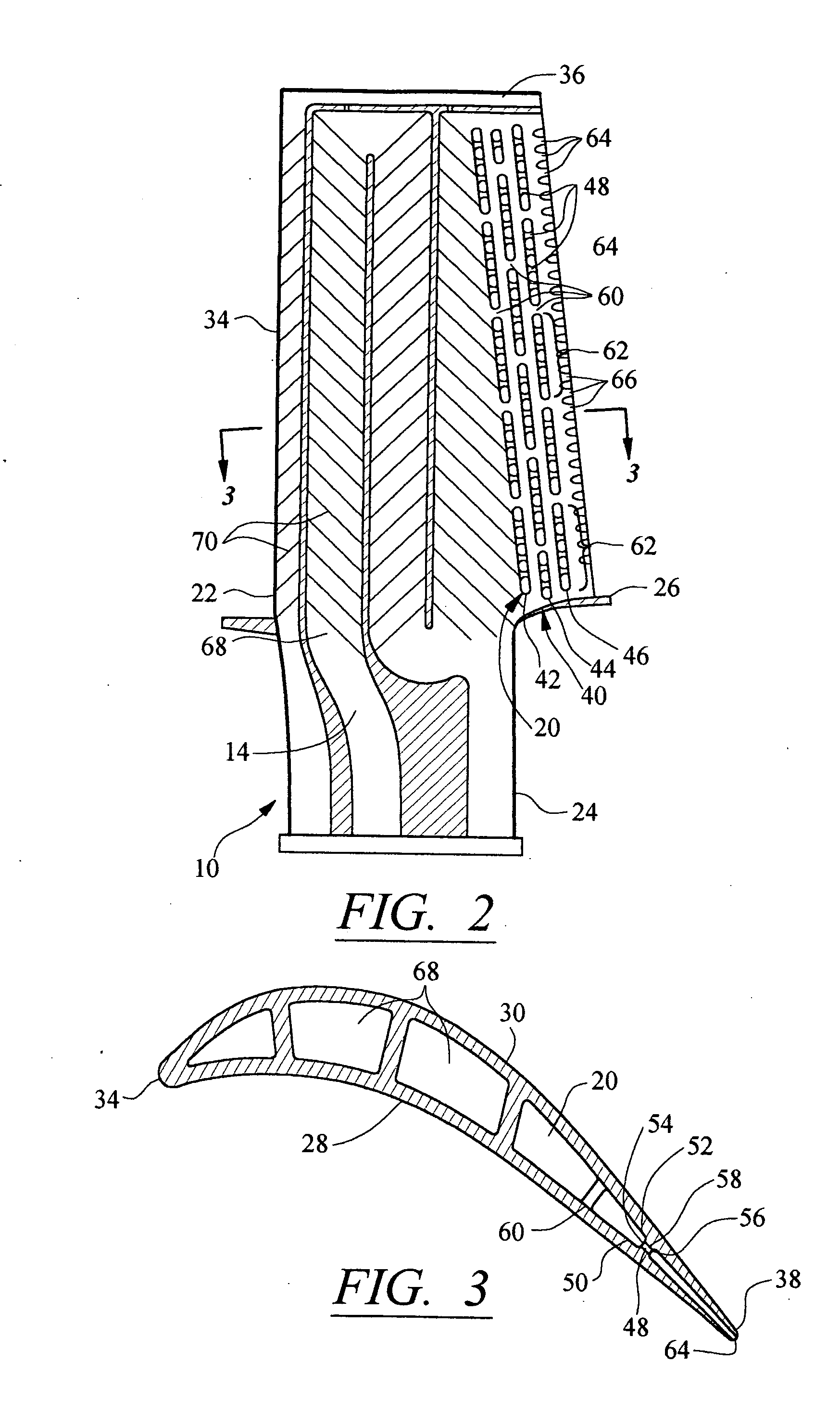
[0025] As shown in FIGS. 1-7, this invention is directed to a turbine airfoil cooling system 10 for turbine airfoil 12 used in turbine engines. In particular, the turbine airfoil cooling system 10 is directed to a cooling system 10 located in a cavity 14, as shown in FIGS. 2-7, positioned between two or more walls 18 forming a housing 16 of the turbine airfoil 12. The cooling system 10 may include a trailing edge cooling channel 20 adapted to receive cooling fluids to reduce the temperature of the turbine airfoil 12 thereby reducing the required cooling fluid flow to achieve adequate cooling and increasing the effectiveness of the cooling system 10. The trailing edge cooling channel 20 may be configured such that during manufacturing of the channel 20, the likelihood of damage to a ceramic core is reduced. The trailing edge cooling channel 20 may be configured such that a ceramic core 68, which forms the cavities 14, used to produce the airfoil 12 has greater structural strength, th...


PUM


Abstract

A cooling system for a turbine airfoil of a turbine engine having multiple segmented ribs aligned together spanwise within a trailing edge cooling channel. The segmented ribs may be positioned proximate to a trailing edge of the turbine airfoil to facilitate increased heat removal with less cooling fluid flow, thereby resulting in increased cooling system efficiency, and to increase the structural integrity of the trailing edge of the airfoil. The segmented ribs may include crossover orifices that provide structural integrity to ceramic cores used during manufacturing to prevent cracking and other damage.

Description

FIELD OF THE INVENTION [0001] This invention is directed generally to turbine airfoils, and more particularly to cooling systems in hollow turbine airfoils. BACKGROUND [0002] Typically, gas turbine engines include a compressor for compressing air, a combustor for mixing the compressed air with fuel and igniting the mixture, and a turbine blade assembly for producing power. Combustors often operate at high temperatures that may exceed 2,500 degrees Fahrenheit. Typical turbine combustor configurations expose turbine blade assemblies to these high temperatures. As a result, turbine blades must be made of materials capable of withstanding such high temperatures. In addition, turbine blades often contain cooling systems for prolonging the life of the blades and reducing the likelihood of failure as a result of excessive temperatures. [0003] Typically, turbine blades are formed from a root portion having a platform at one end and an elongated portion forming a blade that extends outwardly...

Claims


Application Information

Patent Timeline
IPC IPC(8): F01D5/18
CPCF01D5/187F05D2240/122F05D2260/22141B22C9/10F05D2260/202F05D2240/304
Inventor LIANG, GEORGE
Owner SIEMENS ENERGY INC
Why Eureka
Try Eureka