Compression ignition engine

a compression ignition and engine technology, applied in the direction of engine starters, valve arrangements, electrical control, etc., can solve the problems of deteriorating engine startability, increasing the heat loss of compressed air (compressed gas), and dropping the cranking speed

Inactive Publication Date: 2006-12-07
HITACHI LTD
View PDF2 Cites 42 Cited by
  • Summary
  • Abstract
  • Description
  • Claims
  • Application Information

AI Technical Summary

Benefits of technology

[0008] It is, therefore, in view of the previously-described disadvantages of the prior art, an object of the invention to provide a compression ignition engine, capable of avoiding the aforementioned problem that spontaneous ignition of fuel does not take place owing to a drop in cranking speed during a starting period.

Problems solved by technology

The increased work of compression leads to a drop in cranking speed, thereby resulting in an increased heat loss of the compressed air (compressed gas).
As a result of this, a compression temperature, i.e., a temperature of the compressed gas, tends to drop, thus deteriorating the engine startability.
That is to say, the effective compression ratio is controlled to a relatively low ratio, though there is a possibility that the combustion stability is still insufficient just after completion of the starting operation.
This leads to the problem of deteriorated combustion stability.
This leads to another problem of increased manufacturing costs and increased weight.
However, the decompression device itself does not have an effective-compression-ratio reducing function that reduces the effective compression ratio after completion of the starting operation.
Thus, it is difficult to realize the improved fuel economy (i.e., the reduced fuel consumption rate) during normal engine operation, by the use of the decompression device.
However, according to the system of JP1-315631, the effective compression ratio remains high during cranking, thus resulting in an undesirable drop in cranking speed.
This also leads to the problem of reduced cranking speed.
However, even after cranking operation, intake valve closure timing IVC remains retarded, thus deteriorating the engine startability or self-ignitability during start operation.

Method used


Image

  • Compression ignition engine
  • Compression ignition engine
  • Compression ignition engine

Examples


Embodiment Construction

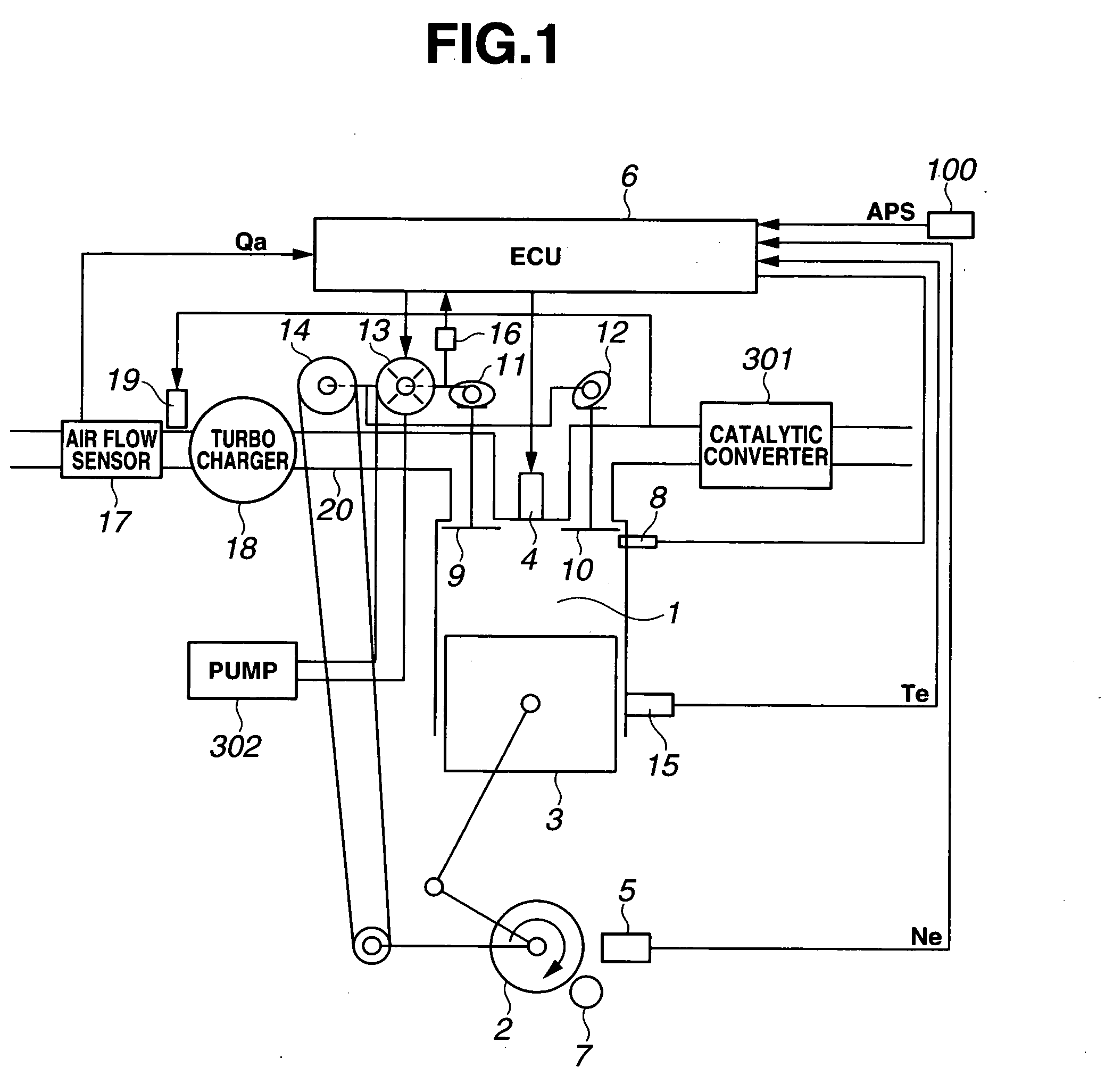
[0034] Referring now to the drawings, particularly to FIG. 1, the variable valve operating system incorporated in the compression ignition engine of the embodiment is exemplified in a four-stroke-cycle engine. As indicated by the arrow in the system block diagram of FIG. 1, a crankshaft 2 of an engine 1 rotates clockwise. As is generally known, a piston position at which a piston 3 has moved to the bottom of the cylinder of engine 1, corresponds to 180 degrees of crank angle. The lowest piston position is called “bottom dead center (BDC)”. A piston position obtained when engine crankshaft 2 further rotates and thus piston 3 has reached the top of the engine cylinder, corresponds to 360 degrees of crank angle. The highest piston position is called “top dead center (TDC)”.

[0035] In the case of usual diesel combustion, diesel fuel (fuel oil) is sprayed or injected via a fuel injection valve 4 into the cylinder during the compression stroke. Then, the sprayed fuel is self-ignited and c...


PUM


Abstract

In a compression ignition engine employing a variable valve actuation mechanism variably adjusting an intake valve characteristic including at least one of an intake valve lift and an intake valve closure timing, a control system operates to temporarily lower an effective compression ratio of the engine by controlling the intake valve characteristic during a cranking period of cold starting operation. At a point of time when a predetermined cranking speed threshold value has been reached owing to a cranking speed rise, the effective compression ratio is risen by controlling the intake valve characteristic. After combustion of the engine has been stabilized, the intake valve characteristic is brought closer to a desired value determined based on engine operating conditions by way of closed-loop control.

Description

TECHNICAL FIELD [0001] The present invention relates to a compression ignition engine employing a variable valve operating system for at least one of intake and exhaust valves, and specifically to the improvement of a compression ignition engine control technology suited to compression ignition engines such as a four-stroke-cycle Diesel engine, a two-stroke-cycle Diesel engine, a premix compression ignition engine, and the like. BACKGROUND ART [0002] In recent years, there have been proposed and developed various engine control technologies for compression ignition engines with variable valve operating systems. Generally, a variable valve operating system, capable of variably adjusting a valve lift and valve timing of at least one of intake and exhaust valves of a reciprocating internal combustion engine depending on engine operating conditions, is widely utilized for controlling a charging efficiency, an effective compression ratio, and an amount of residual gas of the engine, ther...

Claims


Application Information

Patent Timeline
Patent Type & Authority Applications(United States)
IPC IPC(8): F01L13/08
CPCF01L13/0015F02N19/004F02D41/064F01L13/08F01L1/3442F01L2001/0476F01L2001/34423F01L2001/34426F01L2001/34469F01L2001/34479F01L2001/34483
Inventor HARA, SEINOSUKEHOKARI, TOMIOSUGA, SEIJINAKAMURA, MAKOTOWATANABE, MASAHIKO
Owner HITACHI LTD
Why Eureka
Try Eureka