Anchor assembly for safety device

Inactive Publication Date: 2006-12-07
ARVO POLDMAA KATHLEEN POLDMAA ROBYN POLDMAA & DANIEL POLDMAA
View PDF15 Cites 8 Cited by
  • Summary
  • Abstract
  • Description
  • Claims
  • Application Information

AI Technical Summary

Benefits of technology

[0014] wherein the shaft of at least the first spacer is adapted to deform progressively (ie in a prescribed manner) so as to at least partially absorb the kinetic energy applied by a load of a falling object attached to the safety device. Preferably the deformation will occur progressively along the length of the shaft of the spacer starting from below the head and moving towards the securing means. In this way the initial load on the structure is minimised, so that by the time the force reaches the securing means it has been significantly reduced, thereby resulting in less damage to the structure or any roofing material etc associated therewith. Furthermore, the deformation thus caused is visible and serves as an indication that the anchor assembly should be replaced, having been thus used.
[0018] The spacers, including the first and the second spacer, may be adapted to space the bridging member from the structure, such as a purlin or other roof structural member. The first and second spacers may be identical or different. The first and second spacers may be of equal length, in which case the bridging member will be spaced uniformly, that is to say spaced generally parallel to the surface of the structure to which the anchor assembly is attached or they may be of different lengths in order to space the bridging member at an angle with respect to the surface of the structure. Preferably, the first and second spacers are adapted to provide substantially uniform spacing between the bridging member and the structure.
[0019] The securing means for attaching each spacer to the structure includes a variety of means including all known positive engagement means applicable to the invention. For example, the means of fastening may include a clamp. Alternatively, the means of fastening may include a simple threaded bolt and nut arrangement. Preferably, the shaft of the spacer terminates at its lower portion in a threaded bolt. The threaded bolt may be adapted to extend through or into the structure and be threadably engaged therewith. More preferably, the threaded portion may be adapted to extend through the structure and be secured by an element with a corresponding internally threaded bore, such as a retro block, so designed for that purpose. The threaded portion may be secured additionally on the side of the structure from which the shaft extends by a further threaded element, such as a nut. Preferably, the further nut is a cone locknut with a tapered skirt depending from the nut body. The tapered skirt may provide the spacer with added energy absorption capability by progressively deforming as the deforming shaft bears against its internal wall upon application of sufficient load.

Problems solved by technology

It has long been recognised that a primary cause of injuries, particularly to inexperienced workers, arises from falls from elevated building structures resulting sometimes in severe injury or even death.
Whilst the rails may be helpful in most situations, there remains the possibility that an unsecured worker may still topple over the railing.
Anchor points, such as those which may be mounted on exposed beams or rafters, may not be satisfactory as the structural members themselves may not be capable of sustaining the loads necessary to withstand the damage resulting from the impact occasioned by the fall of a worker.
Moreover, such falls will end in a severe jolt to the worker when the full extent of the rope or cable is taken up, which may itself occasion injury.

Method used


Image

  • Anchor assembly for safety device
  • Anchor assembly for safety device
  • Anchor assembly for safety device

Examples


second embodiment

[0059]FIG. 9 shows an anchor assembly (2) again utilising two anchor points including a pair of first spacers (10). Each of the spacers (10) are connected by a bridging plate (50) having spaced apertures as previously described in FIG. 5. As can be seen in FIG. 9, the spacers (10, 10′) may be anchored to discreet structural members (90) rather than a single structural member.

third embodiment

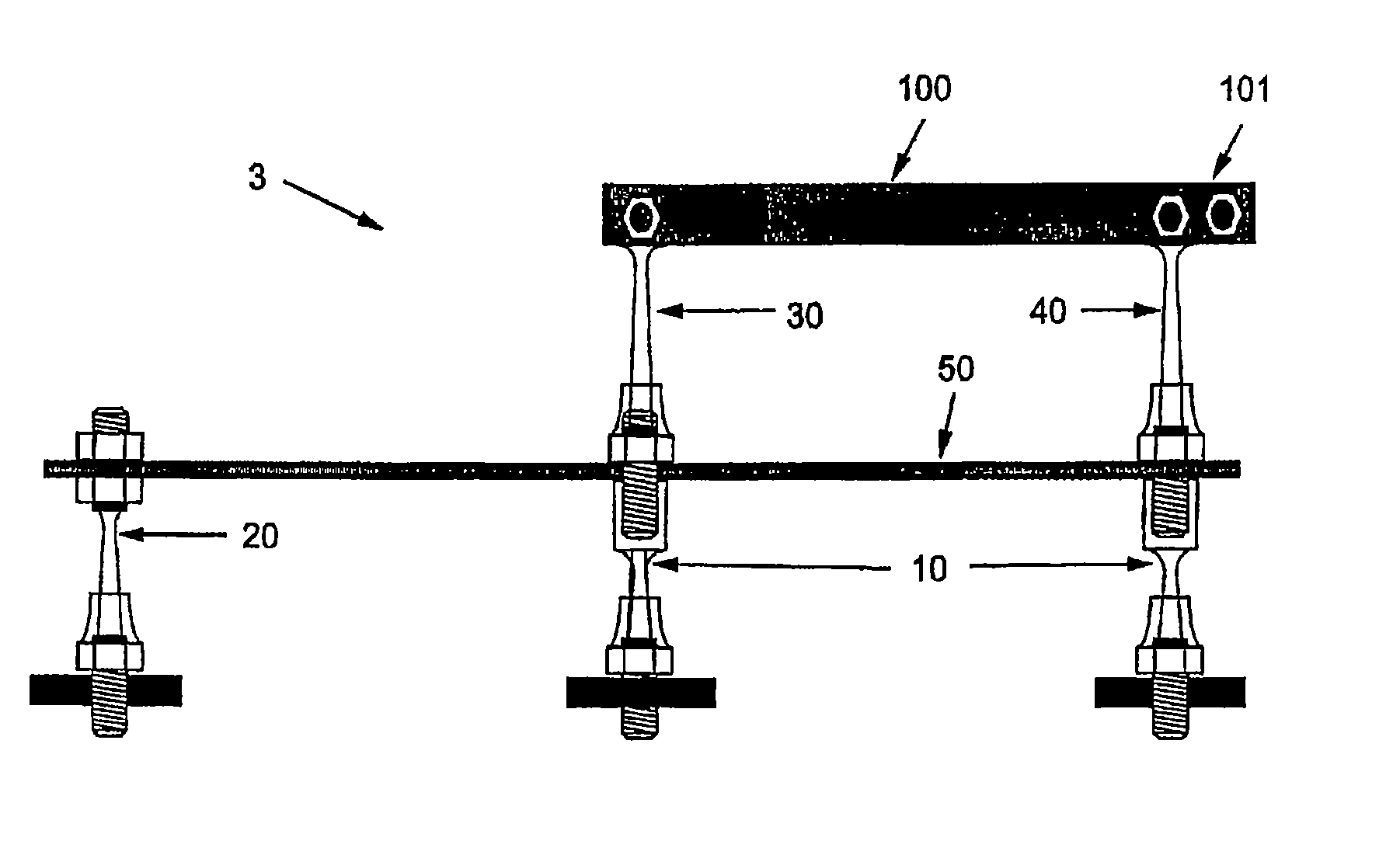
[0060] In FIG. 10 there is shown an anchor assembly (3) in which a pair of eyebolts, for example eyebolts (30, 40), are utilised and secured to the remainder of the third anchor assembly (3) by engagement to a pair of first spacers (10). A bridging plate (50) connects the three spacers (10,20) as previously described in relation to FIG. 8 or 9. The eyebolts (30, 40) are connected at their respective heads (not shown) by a bridging bracket (100) whereby the eyebolt (30) will deform in preference to the spacers (10). The safety device is attached to the third anchor assembly (3) by attachment to the eyelet (101) extending from the end of the bridging bracket (100). In place of solid bridging bracket (100), a turnbuckle may be utilised to provide tension to the assembly (3).

[0061]FIG. 11 shows yet another embodiment (4) utilising three spacers (10, 20) and a pair of eyebolts (30 or 40) in similar arrangement to FIG. 10, except that the assembly (4) has the safety device (eg cable not ...


PUM


Abstract

An anchor assembly (3) for securing at least one safety device indirectly to a structure is disclosed. The anchor assembly includes at least two spacers (10,20), including a first spacer and a second spacer; at least one bridging member (50) spanning between the spacers; and engagement means (30,40) for securing the safety device to the anchor assembly. Each spacer includes securing means for securing the spacer directly to the structure; a head for fastening the spacer to the bridging member and / or to the engagement means; and a shaft extending between the securing means and the head. The shaft of at least the first spacer is adapted to deform progressively so as to at least partially absorb the kinetic energy applied by a load of a falling object attached to the safety device.

Description

CROSS-REFERENCE TO RELATED APPLICATIONS [0001] This application is a continuation of International Application No. PCT / AU2004 / 001405, filed Oct. 14, 2004, which was published in the English language on Apr. 28, 2005, under International Publication No. WO 2005 / 037378 A1 and the disclosure of which is incorporated herein by reference.BACKGROUND OF THE INVENTION [0002] This invention relates to an anchor assembly for one or more safety devices and more particularly, to an anchor assembly for securing one or more safety devices to a structure such as a building. [0003] The building industry is becoming evermore conscious of the need for ensuring the safety of its workers and, indeed, authorities in many jurisdictions have introduced, or are in the process of introducing, recommendations and regulations which seek to make building sites and buildings on which workers must perform their duties safer workplaces. [0004] It has long been recognised that a primary cause of injuries, particul...

Claims


Application Information

Patent Timeline
IPC IPC(8): E04G3/28A62B1/04A62B35/04E04G21/32
CPCA62B1/04A62B35/0056E04G21/3261A62B35/04A62B35/0068E04G21/3276E04G21/328E04G21/329E04G21/3295
Inventor POLDMAA, ARVO
Owner ARVO POLDMAA KATHLEEN POLDMAA ROBYN POLDMAA & DANIEL POLDMAA
Why Eureka
Try Eureka