Apparatus for electron spin resonance CT

a technology of electron spin resonance and imaging apparatus, which is applied in the direction of electron paramagnetic resonance analysis, magnetic measurement, instruments, etc., can solve the problems of difficult to obtain morphological images, the number of mice used for animal experiments is also remarkable, and the cost of new drug development by pharmaceutical companies is dramatically increasing

Inactive Publication Date: 2009-06-02
HITACHI LTD
View PDF6 Cites 4 Cited by
  • Summary
  • Abstract
  • Description
  • Claims
  • Application Information

AI Technical Summary

Benefits of technology

[0034]In accordance with the present invention, the permanent magnet as a static magnetic field generator and the pole pieces are combined through the yokes combined to the magnetic pole planes of the permanent magnet having a junction area which is ⅓ to 1/30 times as small as the opposed areas of the pair of opposed pole pieces, so as to secure a wide gap between the pole pieces. This made it possible to create a static magnetic space suitable for ESR-CT for the living body, in which the residual magnetic flux density Br of the permanent

Problems solved by technology

With the decrease in candidate compounds for new medicines and the increase in attention to security for the human body, the cost of new drug development by pharmaceutical companies is dramatically increasing and accordingly the number of mice used for animal experiment is also remarkably increasing.
Therefore, there has been a problem of finding out a target image from a huge amount of morphological images in order to discover an affected region.
In the case of ESR-CT, since a radical contrast agent specific to ESR is applied to a small animal to image a distribution, it is difficult to obtain morphological images.
When performing diagnostic imaging of the living body of an experimental small animal under anesthesia to alleviate the burden to the living body, the imaging time is limited to about 15 minutes because of the physical strength of the small animal.
In the case of imaging under weak anesthesia or without anesthesia, it is desirable to complete imaging within a shorter period of time because there is a risk that the animal wriggles the body.
With conventional MRI or ESR-CT, there has not been much demand for performing diagnostic imaging of the living body of an experimental small animal, and therefore the problem of the long imaging time has not been emerged as a common problem.
(1) High-speed switching of gradient field cannot be performed.
(2) High-speed field scanning cannot be performed.
(3) It is difficult to image an intentionally targeted region (desired portion) with a high spatial resolution of 1 mm or less.
As a result, high-speed switching of gradient field generates an eddy current in the yokes, resulting in distortions and artifacts in the image.
Therefore, high-speed switching cannot actually be realized.
As a result,

Method used


Image

  • Apparatus for electron spin resonance CT
  • Apparatus for electron spin resonance CT
  • Apparatus for electron spin resonance CT

Examples


first embodiment

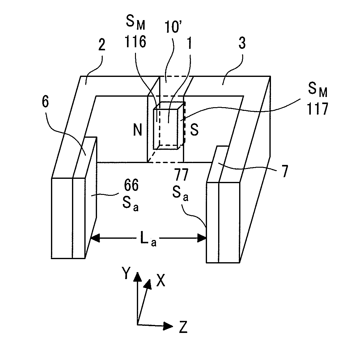
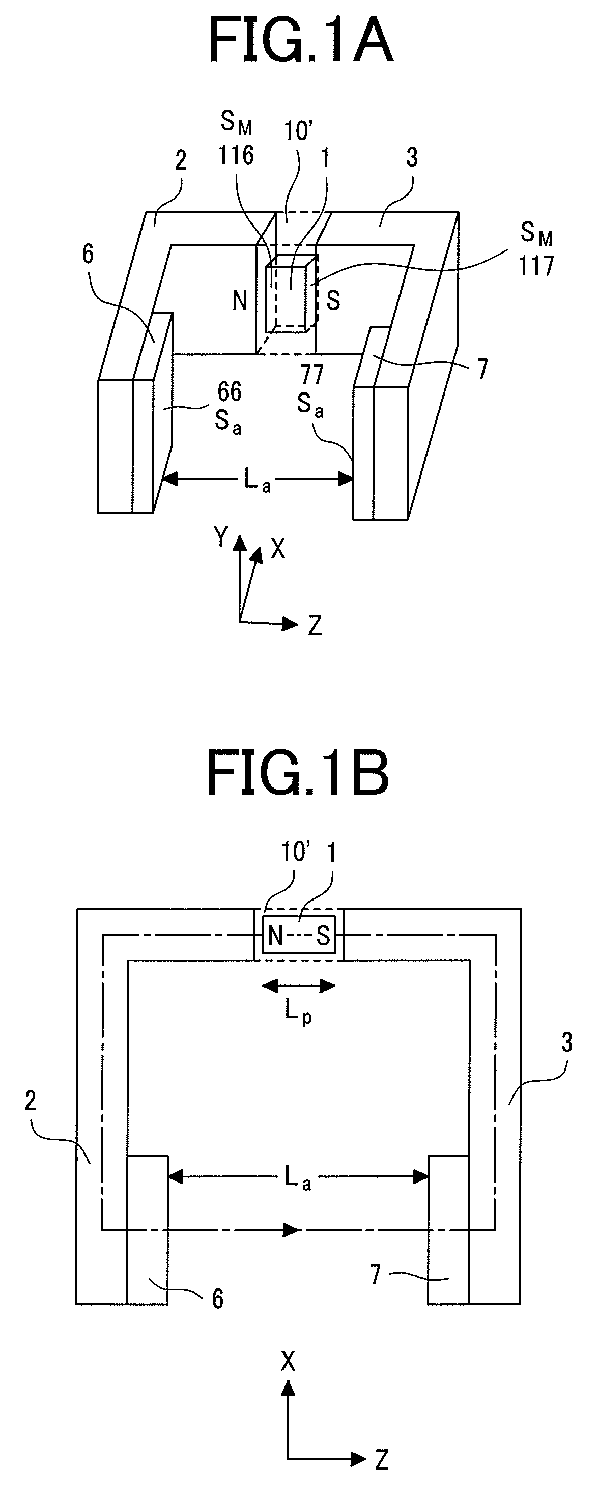
[0143]FIG. 7A is a perspective view showing an appearance of a magnet system for 200-MHz ESR-CT for an embodiment which uses the permanent magnet 1 (FIG. 1) of the present invention as a magnetic field generator. The same components as those in FIG. 1 are assigned the same reference numerals. With an actual structure, as is understood from the comparison with FIG. 1, the end faces of the yokes 2 and 3 are semicircle-shaped and the pole pieces 6 and 7 are disc-shaped. Reference numerals 40 and 41 are casters for transporting the magnet. A reference numeral 1′ is a permanent magnet. This magnet is assigned a reference numeral different from that of the permanent magnet 1 which is embedded in the yokes as shown in FIG. 1.

[0144]In the first embodiment, a main static field strength H0 caused by the permanent magnet 1 is about 71.4 G. This time, the magnitude of the measured space L (a region subjected to imaging, such as a mouse) is set to 35 mm. In order to ensure the long-term stabilit...

second embodiment

[0158]Another embodiment having the basic concept of the present invention is shown below. A second embodiment is ESR-CT targeting a rat which is fairly larger than a mouse. For the second embodiment, technical examples regarding 400-MHz ESR-CT including a movable gradient coil system are shown in FIG. 9A, FIG. 9B, and FIG. 10. The main part of the appearance of the permanent magnet system is shown in FIG. 9A, and a magnetic circuit loop on the Y-Z plane taken along a magnetic line passing the permanent magnet system 101′ is shown by a dashed line in FIG. 9B. In FIG. 9A, the magnet of the permanent magnet system is installed on the X-Z plane, and portions which support the yokes 2 and 3 from outside are omitted. FIG. 10 is a sectional view showing coil arrangements of the permanent magnet system in the magnet field, taken at the center of the permanent magnet 101 and viewed along the X axis. Like the first embodiment shown in FIG. 5, the present embodiment includes a stage 551 which...

third embodiment

[0173]Another embodiment of the zoom-in function of the present invention will be explained below as a third embodiment.

[0174]The third embodiment is another embodiment of the second embodiment. The third embodiment uses the same permanent magnet system as the second embodiment and differs therefrom in that the gradient coil system formed between the pole pieces include both a fixed gradient coil system and a movable gradient coil system. FIG. 11 is a sectional view showing coil arrangements corresponding to FIG. 10 of the second embodiment. The present embodiment will be explained below centering on differences from the second embodiment.

[0175]Unlike the second embodiment, the third embodiment is characterized in that it is provided with a pair of fixed gradient field coils 341 and 351 which images mainly the entire measured space and a pair of movable gradient field coils 340 and 350 which is in charge of the zoom-in function and has a small region subjected to imaging and a large...


PUM


Abstract

A compact, lightweight, and easy-to-use ESR-CT apparatus including a magnetic field leak line (5-G line) which is capable of imaging a small animal, such as a mouse, within 15 minutes, and of observing a desired region with a spatial resolution of 1 mm or less. A permanent magnet system is introduced of the apparatus includes pole pieces having a predetermined area which are opposed to each other through a measured space, yokes combined with the pole pieces, and a permanent magnet inserted in series so that at least one magnetic pole plane intersects perpendicularly to the closed magnetic circuit for magnetic coupling with the yokes. This makes it possible to locate a gradient coil system and a field scanning coil system sufficiently apart from end faces of the pole pieces, and to downsize the field scanning coil system so that the gradient field system is movable.

Description

CLAIM OF PRIORITY[0001]The present invention claims priority from Japanese application JP 2006-245597 filed on Sep. 11, 2006, the content of which is hereby incorporated by reference on to this application.BACKGROUND OF THE INVENTION[0002]The present invention relates to a magnetic field resonance imaging apparatus, and more particularly to a magnetic field resonance imaging apparatus suitable for high-speed imaging with high resolution.[0003]With the decrease in candidate compounds for new medicines and the increase in attention to security for the human body, the cost of new drug development by pharmaceutical companies is dramatically increasing and accordingly the number of mice used for animal experiment is also remarkably increasing. The demand for decreasing the number of small animals used for experiment in the stage of animal experiment called pre-clinic is increasing from the viewpoint of cost reduction and small animal protection. Furthermore, there is an increasing demand...

Claims


Application Information

Patent Timeline
IPC IPC(8): G01V3/00
CPCG01N24/10G01R33/3806G01R33/383
Inventor USAGAWA, TOSHIYUKI
Owner HITACHI LTD
Why Eureka
Try Eureka