Method and apparatus for field-emission high-pressure-discharge laser chemical vapor deposition of free-standing structures

a high-pressure discharge, free-standing technology, applied in chemical vapor deposition coating, metal material coating process, coating, etc., can solve the problems of difficult manual assembly of fibers into systems, inability to manipulate methods into useful structures, and inability to produce functional graded (fg) bulk production methods. to achieve the effect of enhancing the growth rate of free-standing structures

Inactive Publication Date: 2006-12-07
LOS ALAMOS NATIONAL SECURITY
View PDF22 Cites 25 Cited by
  • Summary
  • Abstract
  • Description
  • Claims
  • Application Information

AI Technical Summary

Benefits of technology

[0011] Accordingly, one aspect of the invention is to provide a method of growing a free-standing structure. The method comprises the steps of: providing the free-standing structure, the free-standing structure having a first end and a terminal end, wherein the first end is coupled to a substrate; focusing a laser beam end to heat the terminal end, the laser beam having a beam waist on the terminal; providing at least one gaseous precursor into the beam waist; disposing at least one electrode at a distance from the terminal end, wherein the at least one electrode is in electrical communication with the free-standing structure; and applying a potential between the terminal end and the at least one electrode. The applied potential creates a localized high pressure plasma in the vicinity of the terminal end and generates reactive species from the at least one gaseous precursor and accelerates the reactive species to the terminal end to grow the free-standing structure at an enhanced rate.
[0012] A second aspect of the invention is to provide a method of enhancing the growth rate of a free-standing structure having a terminal end. The method comprises the steps of: heating the terminal end with a laser beam to cause thermionic emission of electrons from the terminal end; providing an electrode, the electrode being in electrical communication with the free-standing structure and disposed at a distance from the terminal end; applying a potential between the terminal end and the electrode to cause field emission from the terminal end; and providing at least one gaseous precursor to the vicinity of the terminal end, wherein the potential between the terminal end and the electrode creates a localized high pressure plasma in the vicinity of the terminal end, generates reactive species from the at least one gaseous precursor, and accelerates the reactive species to the terminal end to enhance the growth rate of the free-standing structure.
[0013] A third aspect of the invention is to provide a method of growing at least one fiber. The method comprises the steps of: depositing one of a seed and a catalyst on a substrate; heating one of the seed and the catalyst with a laser beam, wherein the laser beam has a beam waist; providing at least one gaseous precursor to the beam waist to decompose the at least one gaseous precursor to form the at least one fiber, the at least one fiber having a first end coupled to a substrate and a terminal end; heating the tapered end with the laser beam to cause thermionic emission of electrons from the terminal end; providing an electrode, the electrode being in electrical communication with the fiber and disposed at a distance from the terminal end; applying a potential between the terminal end and the electrode to cause field emission of electrons from the terminal end; and providing at least one gaseous precursor to the vicinity of the terminal end, wherein the potential between the terminal end and the electrode creates a localized high pressure plasma in the vicinity of the terminal end, and wherein the localized high pressure plasma generates reactive species from the at least one gaseous precursor and accelerates the reactive species to the tapered end to enhance the growth rate of the fiber.
[0014] A fourth aspect of the invention is to provide an apparatus for growing a free-standing structure. The apparatus comprises: a support structure for supporting the free-standing structure during growth; at least one gaseous precursor source; a laser that is capable of focusing on a terminal end of the free-standing structure during growth, wherein the laser is capable of heating a growth zone proximate to the terminal end and decomposing species in the growth zone; and at least one electrode, wherein the at least one electrode is in electrical communication with the free-standing structure during growth and is positioned at a distance from the growth zone, and wherein a potential applied between the at least one electrode and the growth zone generates a high pressure plasma and reactive species in the growth zone and accelerates the reactive species to the terminal end to enhance the growth rate of the free-standing structure.

Problems solved by technology

Such methods are frequently not amenable to manipulation into useful structures.
Most bulk production methods are also not amenable to the production of functionally graded (FG) fibers whose composition varies in functionally useful ways along either their lengths or radii.
Scale is also an important factor, as it becomes increasingly difficult to manually assemble fibers into systems as fiber size decreases.
Many materials have yet to be utilized in useful forms such as fibers, simply because either their material properties are not amenable to existing production methods, or the optimal material phase is not thermodynamically stable at the temperatures required by current processing methods.
The use of HfC in composite materials is limited, however, as it has generally only been grown in fiber-like form as random whiskers using chemical vapor deposition.
Drawing HfC wire is impractical, as it is a brittle material.
In addition, deposition kinetics for standard CVD or laser chemical vapor deposition of HfC is relatively slow, driving up the cost of HfC fiber production.
It is, however, impractical to create diamond fibers using traditional thermal CVD or laser chemical vapor deposition because the processing temperatures are greater than the temperature at which diamond becomes thermodynamically unstable.
Current vapor deposition methods are limited in their ability to shape, orient, or assemble fibers, and, in some instances, are unable to achieve fiber growth in the temperature range in which the desired phase is thermodynamically stable.

Method used


Image

  • Method and apparatus for field-emission high-pressure-discharge laser chemical vapor deposition of free-standing structures
  • Method and apparatus for field-emission high-pressure-discharge laser chemical vapor deposition of free-standing structures
  • Method and apparatus for field-emission high-pressure-discharge laser chemical vapor deposition of free-standing structures

Examples


Embodiment Construction

[0021] In the following description, like reference characters designate like or corresponding parts throughout the several views shown in the figures. It is also understood that terms such as “top,”“bottom,”“outward,”“inward,” and the like are words of convenience and are not to be construed as limiting terms. In addition, whenever a group is described as either comprising or consisting of at least one of a group of elements and combinations thereof, it is understood that the group may comprise or consist of any number of those elements, either individually or in combination with each other.

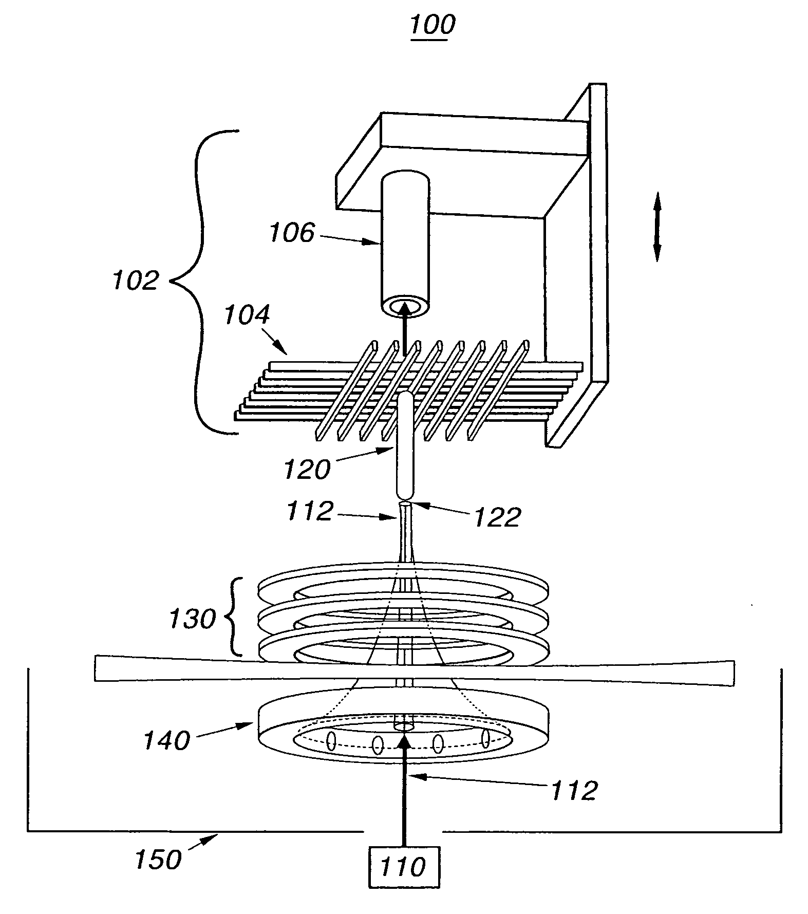
[0022] Referring to the drawings in general and to FIG. 1 in particular, it will be understood that the illustrations are for the purpose of describing a particular embodiment of the invention and are not intended to limit the invention thereto. Turning now to FIG. 1, an apparatus for preparing free-standing structures, as described herein, is shown. For the purposes of understanding the invent...


PUM

PropertyMeasurementUnit
pressureaaaaaaaaaa
pressureaaaaaaaaaa
pressuresaaaaaaaaaa

Abstract

A method of growing a free-standing structure, such as a fiber, rod, or tube. A laser beam having is focused on a terminal end of the fiber to heat the terminal end, and at least one gaseous precursor is provided into the beam. At least one electrode is located at a distance from the terminal end. The electrode is in electrical communication with the free-standing structure. A potential is applied between the terminal end and the at least one electrode. The applied potential creates a localized high pressure plasma in the vicinity of the terminal end, and generates reactive species from the gaseous precursor, and accelerates reactive species to the terminal end to grow the free-standing structure at an enhanced rate. An apparatus for growing fibers according to the method is also disclosed.

Description

STATEMENT REGARDING FEDERAL RIGHTS [0001] This invention was made with government support under Contract No. W-7405-ENG-36 awarded by the U.S. Department of Energy. The government has certain rights in the invention.FIELD OF THE INVENTION [0002] The present invention relates generally to free-standing structures, such as fibers. More particularly, the invention relates to an apparatus and methods for preparing fibers and other structures using plasma enhanced laser chemical vapor deposition. BACKGROUND OF THE INVENTION [0003] Fibers are the simplest three-dimensional microstructures. Fibers find application in a variety of materials applications, including telecommunications, composites, textiles, nanoelectronics, and photonics. Fibers and fiber-like materials are also the basis for many emerging nano-scale (NEMS) and micro-scale electromechanical systems (MEMS) and devices. [0004] The ability to synthesize, shape, place, orient, and assemble fibers is key to their application in su...

Claims


Application Information

Patent Timeline
Patent Type & Authority Applications(United States)
IPC IPC(8): C23C16/52
CPCC23C16/4418C23C16/047
Inventor MAXWELL, JAMES L.BOMAN, MATS
Owner LOS ALAMOS NATIONAL SECURITY
Why Eureka
Try Eureka