

Biosensor strips and methods of preparing same
a technology of biosensor strips and micro-strips, which is applied in the field of biosensor strips, can solve the problems of sample restriction, inaccuracy of reagent registration relative to working electrodes, and inability to accurately register reagents, etc., and achieves the effects of reducing the number of provision openings, and improving the accuracy of positioning
- Summary
- Abstract
- Description
- Claims
- Application Information
AI Technical Summary
Benefits of technology
Problems solved by technology
Method used
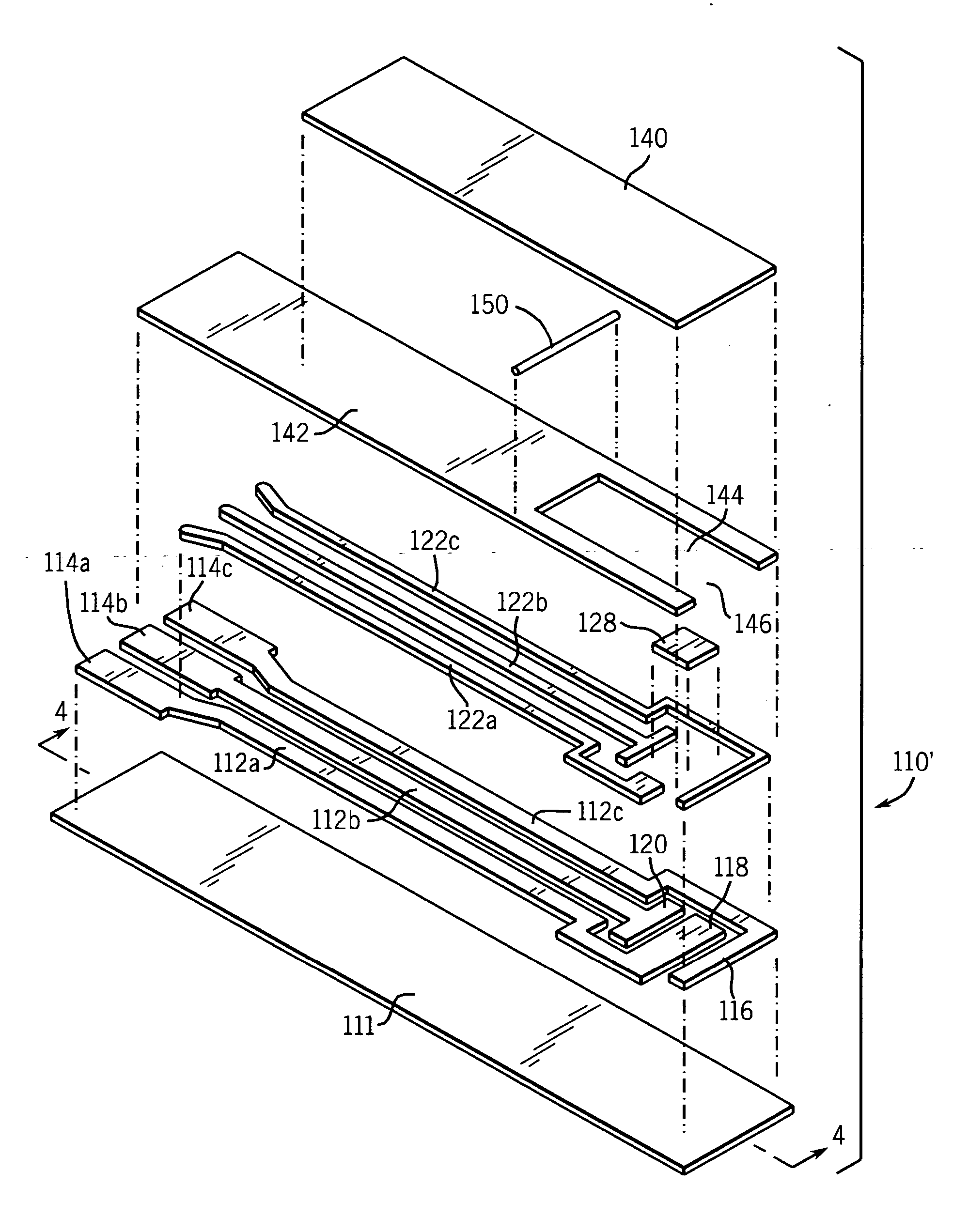
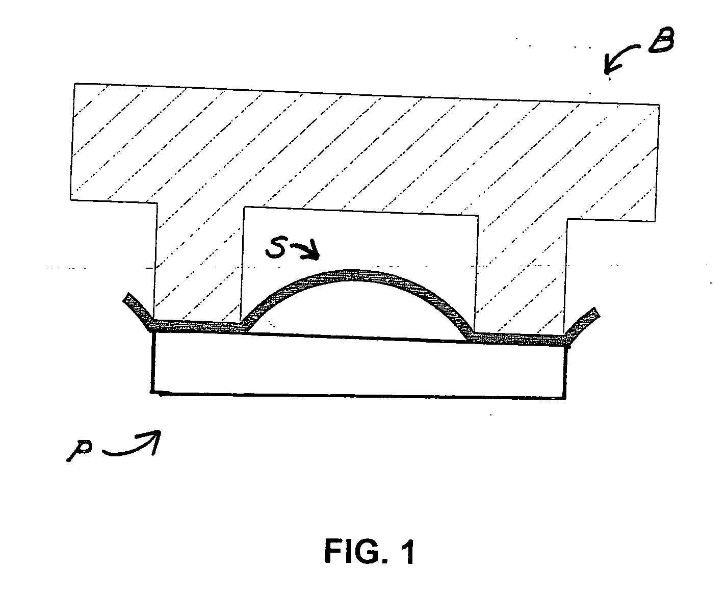
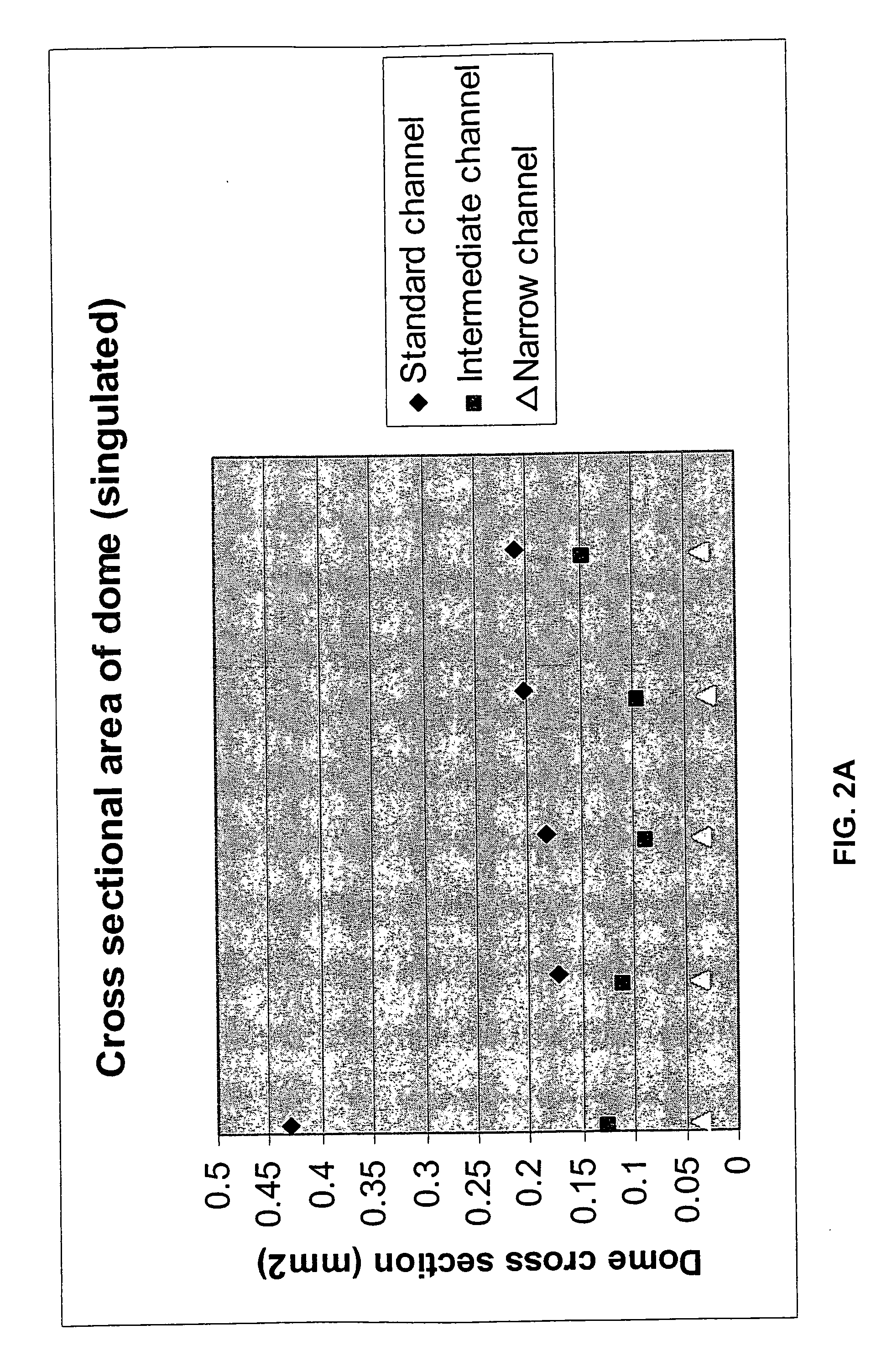
Image

Examples
example 1
[0143] This example illustrates settings for the hot wing apparatus for laminating the cover layer to the remaining layers of a biosensor strip to achieve good adhesion after cutting without the need for corona treatment.
[0144] Cards comprising an electrode support, an electrode arrangement, and a layer of mesh were prepared on a print line and then cut into rows on the windy miller row cutter. Two insulating layers from Sericol were tested. One was lilac (“SERICOL” light blue, LDA 25) and the other green (MediSense part number B03010).
[0145] The hot wing laminator was set at a temperature of 90° C. and 10 volts for the motor speed. There is a substantially direct correlation of speed as a function of voltage, with 18 volts being approximately equal to a tape speed of 21 meters / minute.
[0146] A stack of five (5) rows was prepared for feeding through the apparatus: two scrap rows to consume the tape that had dwelled on the hot wing, then the rows employing (a) the lilac insulating ...
example 2
[0149] The purpose of this example is to establish an average minimum and maximum figure for the displacement of hot melt adhesive into the weave of surfactant coated mesh (FC 170 surfactant, PE 130 mesh) during the lamination process employing the hot wing laminator.
[0150] When tape is removed from a row to which the tape has bonded well, the adhesive that has bonded to the insulating layer remains on the insulating layer and separates from the backing. The area of the adhesive that overlies the sample flow channel, i.e., the area of the mesh that has no insulating layer, remains on the backing that has been removed and the imprint of the mesh can be seen in the adhesive remaining on the backing. The imprint remaining in the adhesive on the backing indicates that displacement of adhesive into the mesh has occurred.
[0151] Samples were processed on the hot wing laminator. The insulating layer was “KROMEX” insulating layer. The hot wing laminator heated the tape (MediSense part numb...
example 3
[0155] The purpose of this example was to identify the cause of the increase in tension experienced with the hot wing laminator. Increased tension on the tape from which the cover is formed results in bowing of the rows from which the biosensors are formed. Increased tension could also cause the row drive system to fail, the tape positional accuracy to wander, and the tape for forming the cover to stretch.
[0156] Openings were formed in the tape by means of a prototype laser apparatus. The speed of the tape was maintained at a constant rate as the tape passed under the laser. The tape handling components were placed under the Universal Laser Systems profile-cutting laser, and the laser beam was fired through the through the rotating shutter disk 304, which has slots to mask the beam at regular intervals, to bring about the perforating action desired.
[0157] Initial tapes formed were laminated to rows on the hot wing laminator with no detrimental effect. The tapes used were 20.5 mm w...
PUM
| Property | Measurement | Unit |
|---|---|---|
| width | aaaaa | aaaaa |
| width | aaaaa | aaaaa |
| width | aaaaa | aaaaa |
Abstract
Description
Claims
Application Information