Biosensors and Methods of Preparing Same

Active Publication Date: 2007-11-29
ABBOTT DIABETES CARE INC
View PDF40 Cites 15 Cited by
  • Summary
  • Abstract
  • Description
  • Claims
  • Application Information

AI Technical Summary

Benefits of technology

[0030] Regardless of the type of adhesive used to adhere the tape to the remaining components of the biosensor strips, this disclosure provides several methods for introducing vents in the biosensor strips. A method for forming openings in the cover of a biosensor strip, which openings require registration in only one direction, is provided. This method simplifies the provision openings in the cover. According to this method, small openings that function as vents can be provided in a tape by preparing the cover by a laser or by mechanical piercing. The openings could be formed in a line and could be separated by specified, typically regular, intervals. The intervals can be selected to ensure that at least one opening, and typically more than one opening, is above each sample chamber after the tape is applied to the remaining components of the biosensor strip, the remainder of the openings becoming redundant. By employing openings formed in this fashion, one of the two directions of registration is no longer necessary, thereby potentially leading to higher production rates and more accurate positioning of at least one vent in the cover of the biosensor strip. In an alternative embodiment, openings can be formed in the electrode support, rather than in the cover of the biosensor strip. More accurate positioning of the tape from which the cover is formed is achieved in a continuous method because the tapes can be maintained under a steady state of tension, thereby rendering the tapes easier to control and position than those tapes subject to intermittent, i.e., stop/start methods, where tension continually increases and decreases.
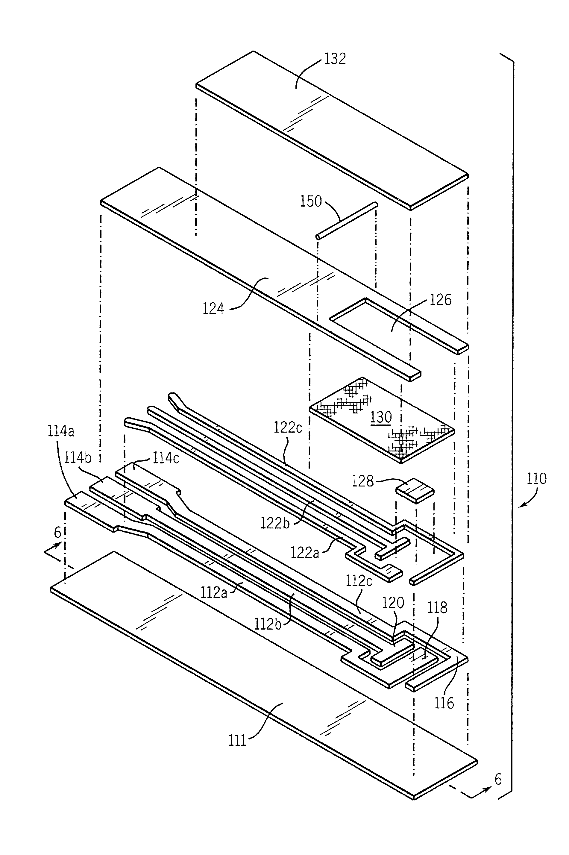
[0031] This disclosure further provides a method for introducing at least one opening in at least one side of the sample chamber or in the distal end (e.g., inlet end) of the sample chamber of the biosensor strip, rather than in the cover or in the electrode support. This method simplifies the provision of vents in the sample chamber. According to this method, small openings that function as vents can be provided by a substantially incompressible element, such as, for example, a thread, a ribbon, or a tape. At least one vent, in one side of the sample chamber or in its distal end, can be formed by providing a row containing a plurality of uncompleted biosensor strips; providing a tape havin

Problems solved by technology

However, placing the reagents over the reference electrode will not influence the electrochemical measurement at the working electrode.
A biosensor having this type of mediator makes it possible for reagents to be applied over the working electrode with inaccurate registration of the reagent relative to the working electrode.
Because this layer of insulating material is hydrophobic, it can cause the sample to be restricted to the portions of the electrodes in the reaction zone.
Proper alignment requires a relatively high degree of skill and considerable time to achieve the bond required for preparing the biosensor strip “S”.
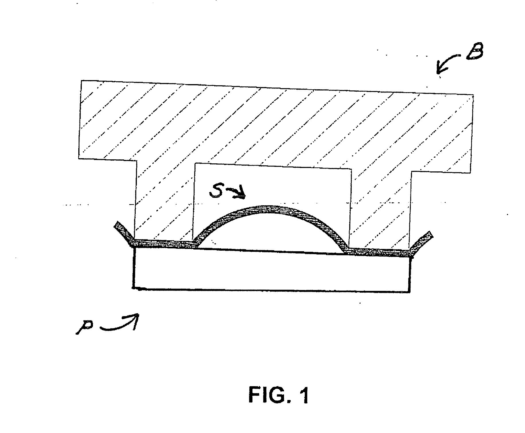
Although this method produces an excellent bond, it may also cause a dome to form in the tape between the points where the portions of the profiled block contact the cover 32.
In addition, the method of application currently used to prepare the biosensor strip is an intermittent process, i.e., lamination of the cover to the remaining layers is not carried out continuously.
Furthermore, reactivating or softening the adhesive while the layer of tape is clamped onto the remaining layers brings about the transfer of a great deal of heat into the remaining layers.
Because enzymes are denatured at elevated temperatures, a high level of heat transfer is not desirable.
Previous trials of low-profile tapes that use pressure-sensitive adhesive (P

Method used


Image

  • Biosensors and Methods of Preparing Same
  • Biosensors and Methods of Preparing Same
  • Biosensors and Methods of Preparing Same

Examples


example 1

[0149] This example illustrated settings for the hot wing apparatus for laminating the cover layer to the remaining layers of a biosensor strip to achieve good adhesion after cutting without the need for corona treatment.

[0150] Cards having an electrode support, an electrode arrangement, and a layer of mesh were prepared on a print line and then cut into rows on the windy miller row cutter. Two insulating layers from Sericol were tested: one was lilac (“SERICOL” light blue, LDA 25) and the other green (MediSense part number B03010).

[0151] The hot wing laminator was set at a temperature of 90° C. and 10 volts for the motor speed. There is a substantially direct correlation of speed as a function of voltage, with 18 volts being approximately equal to a tape speed of 21 meters / minute.

[0152] A stack of five (5) rows was prepared for feeding through the apparatus: two scrap rows to consume the tape that had dwelled on the hot wing, then the rows employing (a) the lilac insulating laye...

example 2

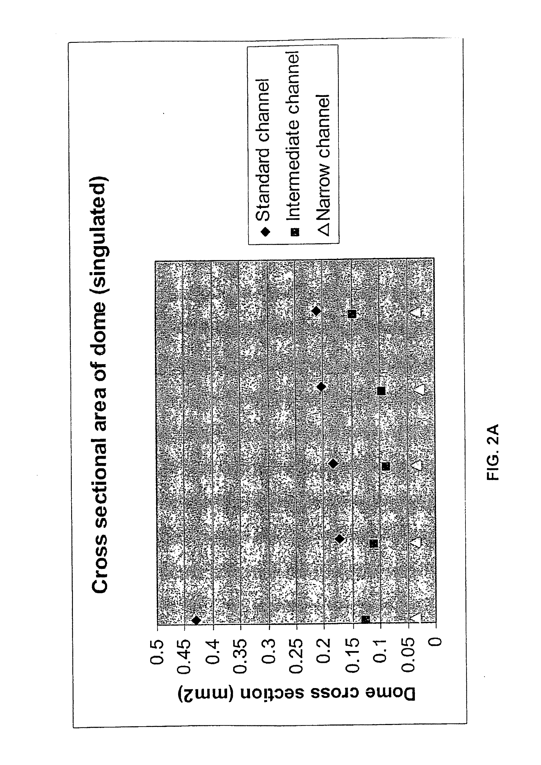
[0155] The purpose of this example was to establish an average minimum and maximum figure for the displacement of hot melt adhesive into the weave of surfactant coated mesh (FC 170 surfactant, PE 130 mesh) during the lamination process employing the hot wing laminator.

[0156] When tape is removed from a row to which the tape has bonded well, the adhesive that has bonded to the insulating layer remains on the insulating layer and separates from the backing. The area of the adhesive that overlies the sample chamber, i.e., the area of the mesh that has no insulating layer, remains on the backing that has been removed and the imprint of the mesh can be seen in the adhesive remaining on the backing. The imprint remaining in the adhesive on the backing indicates that displacement of adhesive into the mesh has occurred.

[0157] Samples were processed on the hot wing laminator. The insulating layer was “KROMEX” insulating layer. The hot wing laminator heated the tape (MediSense part number R...

example 3

[0162] The purpose of this example was to identify the cause of the increase in tension experienced with the hot wing laminator. Increased tension on the tape from which the cover is formed results in bowing of the rows from which the biosensors are formed. Increased tension could also cause the row drive system to fail, the tape positional accuracy to wander, and the tape for forming the cover to stretch.

[0163] Openings were formed in the tape by means of a prototype laser apparatus. The speed of the tape was maintained at a constant rate as the tape passed under the laser. The tape handling components were placed under the Universal Laser Systems profile-cutting laser, and the laser beam was fired through the through the rotating shutter disk 304, which has slots to mask the beam at regular intervals, to bring about the perforating action desired.

[0164] Initial tapes formed were laminated to rows on the hot wing laminator with no detrimental effect. The tapes used were 20.5 mm w...


PUM

PropertyMeasurementUnit
Timeaaaaaaaaaa
Timeaaaaaaaaaa
Timeaaaaaaaaaa

Abstract

A biosensor strip having a low profile for reducing the volume of liquid sample needed to perform an assay. In one embodiment, the biosensor strip includes an electrode support; an electrode arrangement on the electrode support; a cover; a sample chamber; and an incompressible element placed between the cover and the electrode support, the incompressible element providing an opening in at least one side or in the distal end of the sample chamber to provide at least one vent in the sample chamber. In another embodiment, the biosensor strip has an electrode support; an electrode arrangement on the electrode support; a cover; and a sample chamber, the cover having a plurality of openings formed therein, at least one of the openings in register with the sample chamber. The invention further includes methods for preparing such a biosensor strips in a continuous manner.

Description

[0001] This application is a continuation-in-part application of co-pending application having Ser. No. 11 / 147,532, filed Jun. 8, 2005, the entire disclosure of which is incorporated by reference herein.BACKGROUND OF THE INVENTION [0002] 1. Field of the Invention [0003] This disclosure relates to biosensor strips and methods for preparing biosensor strips. [0004] 2. Discussion of the Art [0005] An electrochemical cell is a device that has a working electrode and a counter electrode, which electrodes are connected to one another electrically. When in use, electrochemical reactions occurring at each of the electrodes cause electrons to flow to and from the electrodes, thus generating a current. An electrochemical cell can be set up either to harness the electrical current produced, for example in the form of a battery, or to detect electrochemical reactions which are induced by an applied current or voltage. [0006] A biosensor is a type of electrochemical cell, in which the electrode ...

Claims


Application Information

Patent Timeline
IPC IPC(8): G01N33/487
CPCC12Q1/001Y10T156/1052G01N27/327G01N27/3272C12Q1/006
Inventor PETYT, ADRIANBATES, MATTREID, PAMELABULL, ANDYGARNER, JEFF
Owner ABBOTT DIABETES CARE INC
Why Eureka
Try Eureka