Optical receiver and optical receiving method corresponding to differential M-phase shift keying system

a technology of optical receiver and optical receiving method, which is applied in the direction of optical elements, instruments, digital transmission, etc., can solve the problems of large optical receiver size, inability to avoid enlargement of optical receiver, and the need for high-quality optical phase control technology between delay interferometers, etc., and achieves low cost and small size

Inactive Publication Date: 2006-12-14
FUJITSU LTD
View PDF2 Cites 52 Cited by
  • Summary
  • Abstract
  • Description
  • Claims
  • Application Information

AI Technical Summary

Benefits of technology

[0014] The present invention has been proposed by placing the focus to the point explained above. It is therefore an object of the present invention to provide a small size and low cost optical receiver which can demodulate stably the signal light in accordance with the differential M-phase shift keying (DMPSK) system.
[0016] According to the optical receiver of the present invention, since the process of the differential M-phase shift keying signal light which has been conducted in the background art by allocating the delay interferometers of two systems on the two substrates is in turn realized in the present invention by allocating the delay interferometer of each system on one substrate, it is possible in the present invention to provide a small size and stable optical receiver even when the light wavelength of the receiving signal varies. Moreover, it is also possible to provide an optical receiver which can receive the multirate signal lights in the stabilized signal quality.

Problems solved by technology

However, the optical receiver of the background art as illustrated in FIG. 10 has a problem that two delay interferometers including rather long optical paths for delaying the time of a symbol must be provided and thereby the optical receiver tend to be large in size.
In the case where such delay interferometer is realized with an optical waveguide formed on the silica substrate or the like, a pair of optical waveguide circuits of large area must be allocated and therefore it is impossible to avoid enlargement of the optical receiver.
Moreover, in the optical receiver of the background art, since the interference operating point (i.e. optical phase) of one delay interferometer must be set accurately to π / 4, while the operating point of the other delay interferometer must be set, also accurately, to −π / 4, here rises also a problem that a technology is required to control optical phase with high accuracy between the delay interferometers.
Here rises a problem also that since one operating point exists substantially for the interference, the technique for realizing a multirate optical receiver of the differential M-phase shift keying in different transmission rates is required.

Method used


Image

  • Optical receiver and optical receiving method corresponding to differential M-phase shift keying system
  • Optical receiver and optical receiving method corresponding to differential M-phase shift keying system
  • Optical receiver and optical receiving method corresponding to differential M-phase shift keying system

Examples


first embodiment

[0041] [First Embodiment]

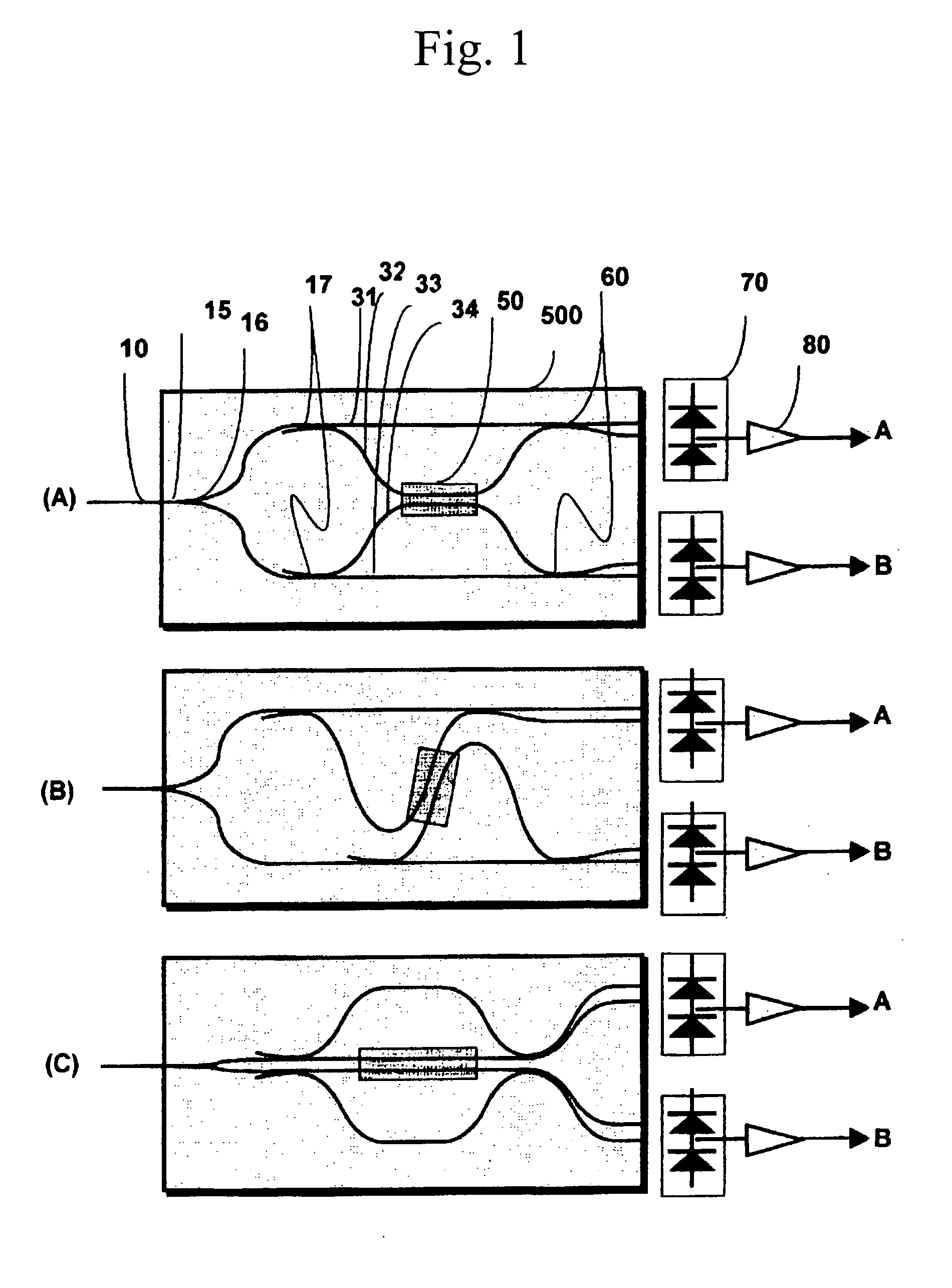
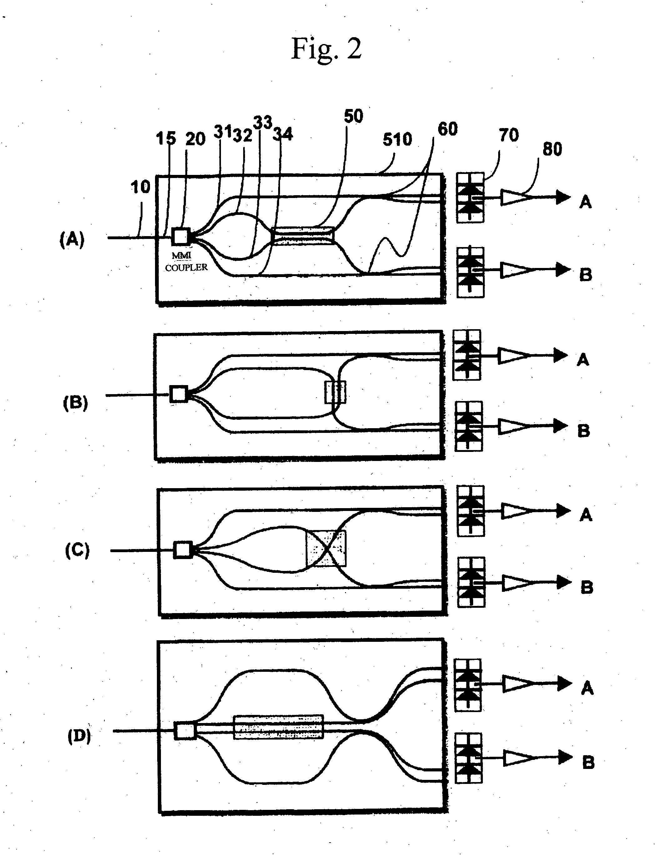
[0042]FIG. 1(A) is a block diagram illustrating a basic structure of an optical receiver as a first embodiment of the present invention. First, the basic structure will be explained with inclusion of each principal portion. In this Figure, the reference numeral 500 is a silica substrate or indium phosphide substrate. The delay interferometers for two systems are integrated on one planar lightwave circuit (PLC) for reduction in size. Numeral 10 denotes a single mode fiber; 15, an optical waveguide; 16, 17, light branching units formed of a light directional coupler for almost equally branching the input DQPSK signal into two signal lights; 31 to 34, optical waveguides where the four signal lights having almost equal power are branched with the light branching units 16, 17 to the optical waveguides 31 to 34; 50, a light path length varying unit which is formed, for example, of a thin film heater for varying temperature in regard to the equal length of a part o...

second embodiment

[0087] [Second Embodiment]

[0088]FIG. 1(B) illustrates a modification example of the optical receiver as the first embodiment (FIG. 1A) of the present invention. This embodiment is different from the first embodiment in the point that the optical waveguides 31 and 32 in the first embodiment are arranged asymmetrically on the substrate and the light path length varying unit 50 is arranged diagonally to the fiber 10.

[0089] Namely, two optical waveguides are arranged asymmetrically and the heater can be arranged diagonally. Particularly, this arrangement is useful when there are limitations on the mounting method and influence of temperature.

third embodiment

[0090] [Third Embodiment]

[0091]FIG. 1(C) illustrates a modification example of the optical receiver as the first embodiment (FIG. 1A) of the present invention. In the first and second embodiments, the light path length varying unit for phase adjustment has been provided to the relative delay optical waveguides 32, 33 corresponding to a symbol. However, this embodiment is different in the point that the light path length varying unit 50 is arranged to the other optical waveguides 31, 34. With this arrangement, the thin film heater, for example, can be arranged in the longer length. Particularly, this structure is useful when sufficient reduction in size is realized and thereby the operating points of the two delay interferometers cannot easily provide the light path difference of +π / 4 and −π / 4 as the relative phase difference explained above through the control of the light path length varying unit 50.


PUM

PropertyMeasurementUnit
delay timeaaaaaaaaaa
shift angleaaaaaaaaaa
timeaaaaaaaaaa

Abstract

An optical receiver comprises branching units for branching and supplying the signal lights to be inputted to the first to fourth optical waveguides provided on a substrate, second to third optical waveguides for giving delay time differences corresponding to a symbol of the DMPSK modulated signal, a demodulating unit for demodulating two light signals through interference of signal lights between the first to second optical waveguides and between the third to fourth optical waveguides, two optical detectors for converting two light signals from the demodulating unit, and a light path length varying unit for identically varying each light path length of two optical waveguides being arranged through selection of combinations of the first and third optical waveguides, the first and fourth optical waveguides, and the second and third optical waveguides in one region when the wavelength of the signal light is varied.

Description

FIELD OF THE INVENTION [0001] The present invention relates to an optical receiver and an optical receiving method for demodulating the signal light of the differential M-phase shift keying and particularly to a technique for realizing a small size optical receiver of the DQPSK ensuring stable operation. BACKGROUND OF THE INVENTION [0002] In recent years, attention has been paid, for example, to the optical modulation system such as the differential binary phase shift keying (DBPSK or DPSK) or the differential quadrature phase shift keying (DQPSK) as the technique for enabling high bit rate optical transmission of 40 Gb / s or more per wavelength. [0003] As the requirement of the optical modulation system in the photonic network corresponding to high bit rate, it is expected to have the excellent characteristics for the technical items listed up, for example, in regard to optical noise tolerance, chromatic dispersion tolerance, polarization mode dispersion (PMD) tolerance, optical non...

Claims


Application Information

Patent Timeline
Patent Type & Authority Applications(United States)
IPC IPC(8): H04B10/04H04B10/40G02F1/01H04B10/50H04B10/516H04B10/548H04B10/588H04B10/60H04B10/61H04B10/67
CPCH04B10/60H04L27/2331H04L27/223
Inventor ONAKA, HIROSHIHOSHIDA, TAKESHI
Owner FUJITSU LTD
Why Eureka
Try Eureka