Optical receiver having bias circuit for avalanche photodiode with wide dynamic range

a technology of optical receiver and avalanche, which is applied in the field of optical receivers, can solve problems such as saturation of the output of a/d-c, and achieve the effect of low optical input power and high accuracy

Active Publication Date: 2006-12-14
SUMITOMO ELECTRIC IND LTD
View PDF83 Cites 21 Cited by
  • Summary
  • Abstract
  • Description
  • Claims
  • Application Information

AI Technical Summary

Benefits of technology

[0015] Since the second current sensor has a dynamic range set wider than that of the first current sensor, it can follow input powers of the optical signal and can protect the avalanche photodiode from transient current. On the other hand, the first current sensor enables control of the bias voltage with higher accuracy for low optical input powers.

Problems solved by technology

However, an input voltage range that can be converted into a digital signal by A / D-C is dependent on a reference voltage supplied to the A / D-C, and the increase in the resistance of the current sensing resistor will result in increase of the input into the A / D-C, which causes saturation of the output of the A / D-C.

Method used


Image

  • Optical receiver having bias circuit for avalanche photodiode with wide dynamic range
  • Optical receiver having bias circuit for avalanche photodiode with wide dynamic range
  • Optical receiver having bias circuit for avalanche photodiode with wide dynamic range

Examples


first embodiment

[0022] (First Embodiment)

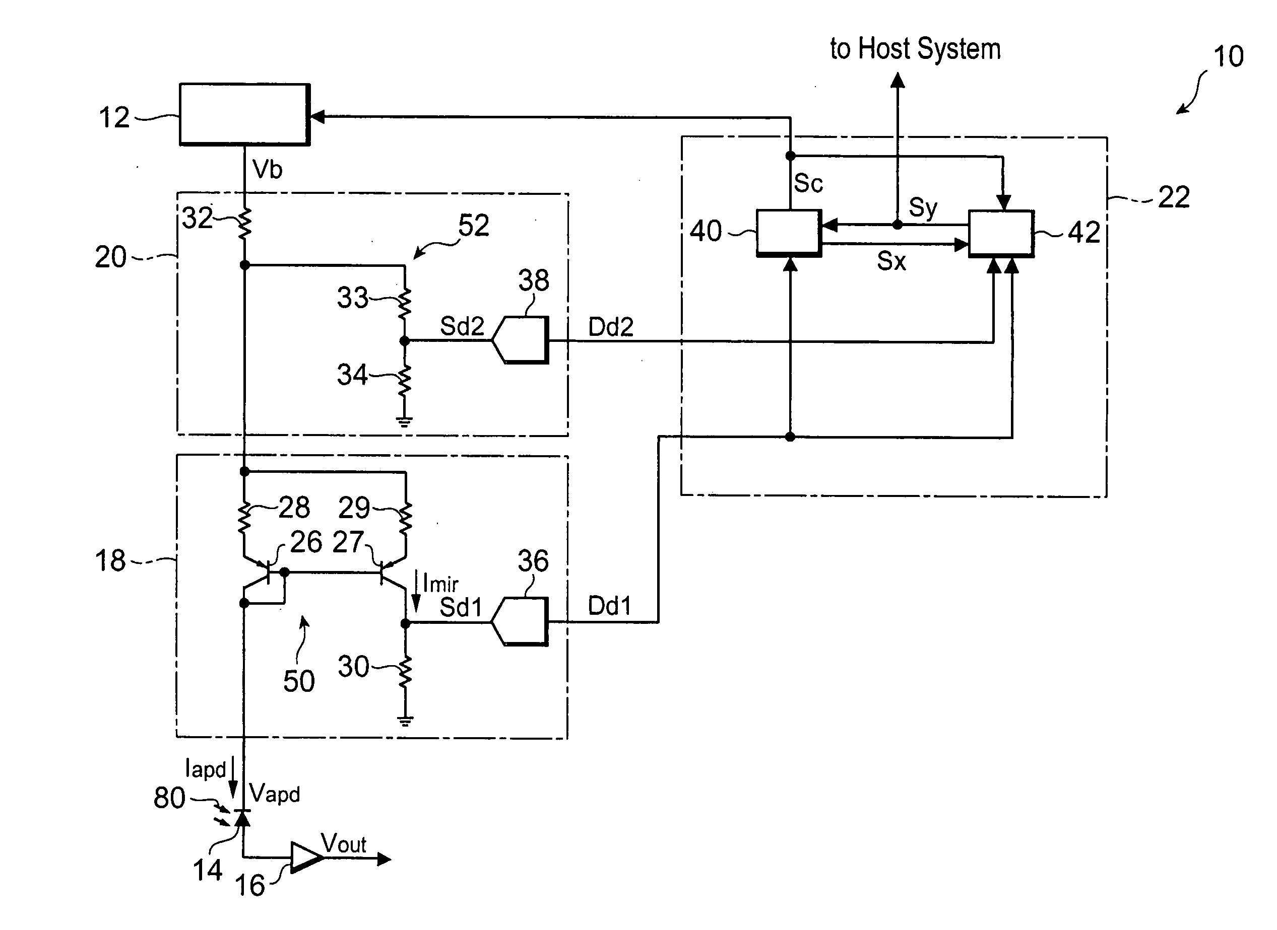
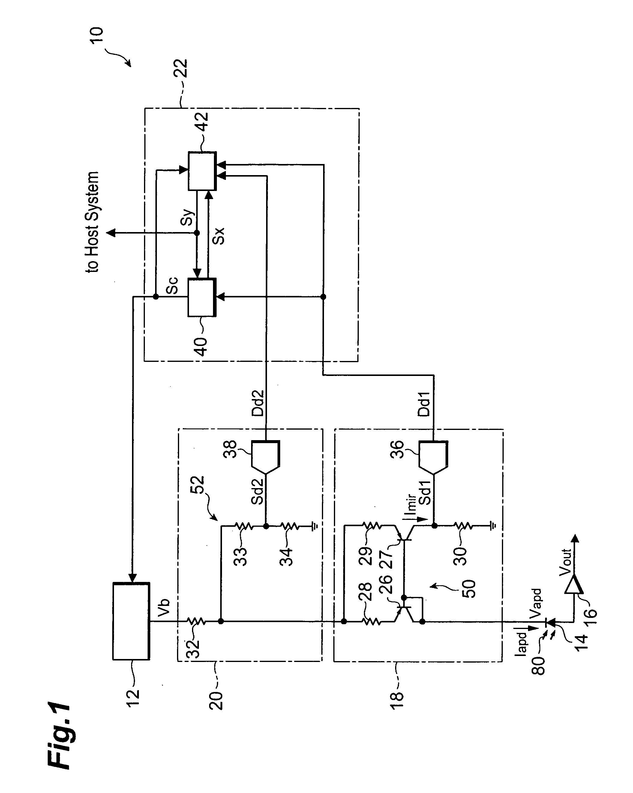
[0023]FIG. 1 is a circuit diagram showing the configuration of an optical receiver according to the first embodiment. The optical receiver 10 has a bias generator 12, an avalanche photodiode (which will be referred to hereinafter as “APD”) 14, a trans-impedance amplifier 16, a first current sensor 18, a second current sensor 20, and a controller 22.

[0024] The bias generator 12 is a voltage source that applies a voltage Vb to the APD 14 in the reverse direction. The output Vb is determined according to a control signal Sc sent from the controller 22. As guided from the bias generator 12 through the two current detecting circuits 18, 20, a bias voltage Vapd is applied to the APD 14. The APD 14 detects an optical signal 80 and converts it into a photocurrent Iapd at a multiplication factor M dependent on the bias voltage. The trans-impedance amplifier 16 for converting the photocurrent Iapd into a voltage signal Vout is connected to the anode of the APD 14.

[0...

second embodiment

[0050] (Second Embodiment)

[0051]FIG. 5 is a circuit diagram showing the configuration of an optical receiver according to the second embodiment. This optical receiver 10a is different from the optical receiver 10 in that the optical receiver 10a has first and second current sensors 18a, 20a resulting from modification of those 18, 20, instead thereof, and in that it has a new controller 22a instead of the controller 22.

[0052] The first current sensor 18a has an amplifier 64 between the sensing resistor 30 and the A / D-C 36. The amplifier 64 amplifies the voltage generated in the sensing resistor 30 at a predetermined amplification factor to generate a signal Sd1. The A / D-C 36 converts the signal Sd1 into a first detected signal Dd1 and feeds it to the controller 22a.

[0053] The output of the amplifier is clamped at a supply voltage supplied to the amplifier. Namely, the amplifier serves as an amplitude limiting circuit. Assuming that the supplied voltage of amplifier 64 is approxima...


PUM


Abstract

An optical receiver is provided as a device capable of detecting a small optical power with satisfactory accuracy and detecting the optical power in a wide dynamic range. In the optical receiver a bias generator applies a variable voltage to an avalanche photodiode (APD). First and second current sensors generate first and second detected signals according to a photocurrent. A controller calculates an optical power, using either one of the detected signals. The first current sensor includes a current mirror circuit and generates a first detected signal by measuring an electric current proportional to the photocurrent. The second current sensor is disposed between the bias generator and the current mirror circuit, and the maximum of the photocurrent detectable by this second current sensor is greater than the maximum of the photocurrent detectable by the first current sensor.

Description

BACKGROUND OF THE INVENTION [0001] 1. Technical Field [0002] The present invention relates to an optical receiver and, particularly, to an optical receiver using an avalanche photodiode. [0003] 2. Related Prior Art [0004] For preventing an avalanche photodiode (APD) from being broken by overcurrent, there are known optical receivers configured to detect the optical power of input light received by the APD and to control the bias voltage applied to the APD. [0005] The Japanese patent application laid open as JP-H11-186971A or the Japanese patent application laid open as JP-2004-289206A discloses a circuit for letting a current mirror circuit produce a mirrored current which reflects a photocurrent flowing in the APD, and for converting this mirrored current into a voltage. An analog-to-digital converter (A / D-C) converts this voltage into a digital signal and the bias voltage supplied to the APD is controlled based thereon. [0006] Normally, the optical receiver is connected to a host ...

Claims


Application Information

Patent Timeline
Patent Type & Authority Applications(United States)
IPC IPC(8): H04B10/06H04B10/40H01L31/10H03F3/08H04B10/07H04B10/50H04B10/60H04B10/67H04B10/69
CPCH04B10/6911
Inventor FUTAMI, RYUTARO
Owner SUMITOMO ELECTRIC IND LTD
Why Eureka
Try Eureka