Speaker member and method for manufacturing the same

a technology of speaker and body, applied in the field of speaker body, can solve the problems of insufficient s/n ratio of metal foil, poor releasability of speaker or edge, and material differences, and achieve the effects of good releasability, excellent moist heat resistance, and light resistan

Inactive Publication Date: 2006-12-14
ONKYO KK
View PDF13 Cites 17 Cited by
  • Summary
  • Abstract
  • Description
  • Claims
  • Application Information

AI Technical Summary

Benefits of technology

[0010] The present invention has been made in view of solving the above-described conventional problems, and an object of the present invention is therefore to provide a speaker member, which is light in weight, and has excellent internal loss and strength, stability in qualities such as heat resistance, moist heat resistance, and light resistance, and excellent moldability, and a simple and inexpensive method of manufacturing the same.
[0027] According to the present invention, the speaker member includes abase material; and a resin film layer laminated on the base material through an adhesive layer, in which: the adhesive layer and the resin film layer each have a predetermined heat shrinkage ratio; and the heat shrinkage ratio of the adhesive layer is smaller than the heat shrinkage ratio of the resin film layer. Thus, the present invention can provide a speaker member having excellent moist heat resistance, light resistance, and heat resistance. Delamination between the resin film layer and the adhesive layer due to heat hardly occurs in the speaker member of the present invention, to thereby presumably provide such an effect. Further, in an embodiment where polycarbonate-based polyurethane is used for the adhesive layer, seepage of the adhesive from the back surface of the base material may be suppressed. Thus, when the speaker member or an edge is molded into a predetermined shape, releasability of the speaker or the edge is favorable.

Problems solved by technology

However, those materials each have problems.
As a result, the metal foil provides an insufficient S / N ratio.
As a result, the engineering plastic provides a small S / N ratio, thereby only providing speakers with much sound distortion.
Further, the engineering plastic generally has a large specific gravity, to thereby cause a problem of reducing sound pressure.
This technique is intended to cause internal friction during vibration owing to the coating.
However, this technique not only adds to a problem of reducing sound pressure by further increased weight but also causes a problem of unstable quality due to uneven thickness of the coating.
However, a general polyurethane resin contains as a main component a polyester-based or polyether-based resin, and has problems such as progression of hydrolysis by humidity and degradation through oxidation decomposition of a carbon main chain by UV irradiation.
Further, the polyether-based resin has a disadvantage of a lower heat decomposition temperature than that of the polyester-based resin, so the polyether-based resin is inferior in heat resistance.
As a result, releasability of a speaker member or an edge degrades, thereby causing molding defects.
Further, adhesiveness between the base material and the laminate film degrades.
However, the lamination must be performed at a temperature at which the thermosetting resin impregnated for shaping of the base material is not yet completely cured.
Thus, a film having a low softening point, that is, a film with insufficient heat resistance must be used.
Further, a large difference in heat shrinkage ratios between the thermoplastic urethane resin film and the adhesive causes a problem of delamination during heating (such as during molding).
In the wet lamination method, the adhesive may seep out from the back surface of the fibrous base material through the press rolls in the step of attaching the fibrous base material, to thereby possibly cause molding defects.

Method used


Image

  • Speaker member and method for manufacturing the same
  • Speaker member and method for manufacturing the same
  • Speaker member and method for manufacturing the same

Examples


example 1

a. Formation of Resin Film Layer

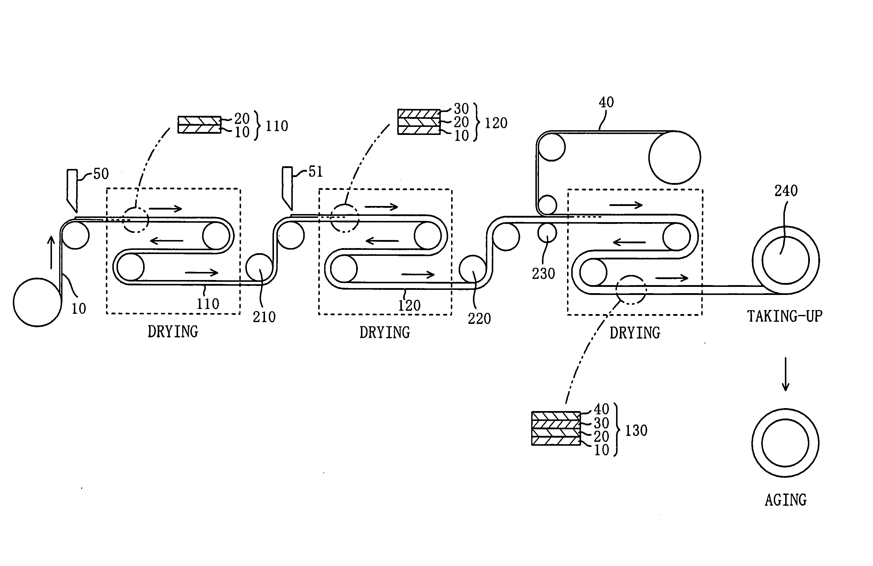
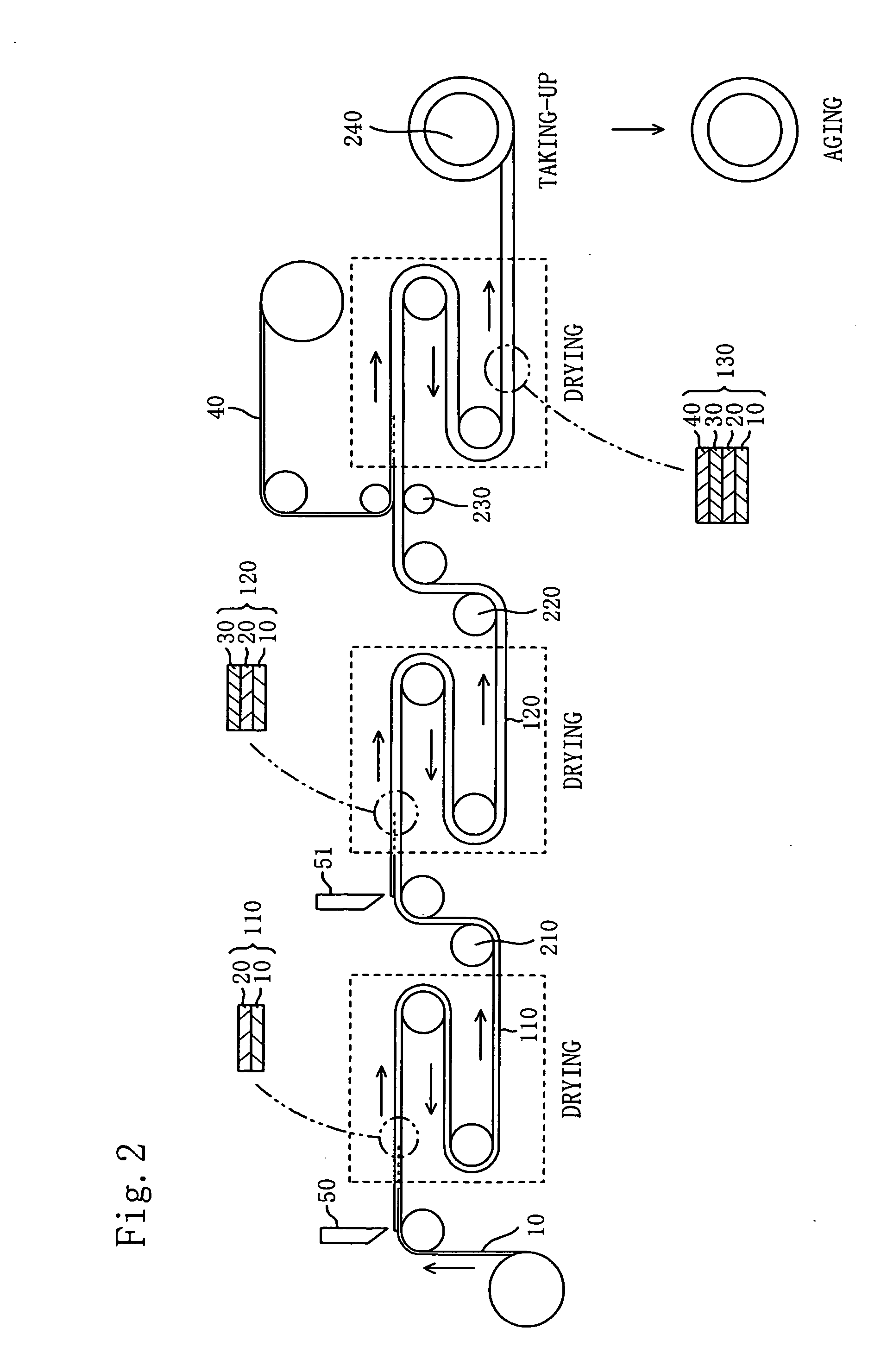
[0069] On a release material with a flat surface, a polycarbonate-based urethane resin solution (20% solid content) was applied by using a doctor knife coater (clearance with a doctor knife blade of 0.1 mm) such that a thickness after drying was 20 μm. The laminate was dried under heating at 80° C. for 10 minutes, to thereby obtain a polycarbonate-based urethane resin film (heat shrinkage ratio of 0.8 to 1.3%).

b. Formation of Adhesive Layer

[0070] On the polycarbonate-based urethane resin film obtained in the step described above, a polycarbonate-based urethane adhesive was applied by using a doctor knife coater (clearance with a doctor knife blade of 0.1 mm) such that a thickness after drying was 30 μm. The whole was dried under heating at 80° C. for 10 minutes, to thereby form a semi-wet adhesive layer (heat shrinkage ratio of 0.5 to 1.0%).

c. Lamination of Base Material

[0071] To the laminate having the adhesive layer formed thereon, a woven f...

example 2

[0076] On the urethane resin film layer obtained in Example 1, a polycarbonate-based urethane adhesive for wet lamination (molecular weight of about 50,000 to 100,000) was applied by using a doctor knife coater (clearance with a doctor knife blade of 0.1 mm) such that a thickness after drying was 30 μm. Then, the whole was dried under heating at 80° C. for 10 minutes, to thereby form a second adhesive layer (heat shrinkage ratio of 0.6 to 1.0%) in a wet state. Further, a polycarbonate-based urethane adhesive for dry lamination (molecular weight of about 20,000 to 50,000) was applied thereon by using a doctor knife coater (clearance with a doctor knife blade of 0.1 mm) such that a thickness after drying was 30 μm. The whole was dried under heating at 80° C for 10 minutes, to thereby form a first adhesive layer (heat shrinkage ratio of 0.5 to 0.8%). A speaker member was molded in the same manner as in Example 1 except that those adhesive layers were used. The obtained speaker member w...


PUM

PropertyMeasurementUnit
thicknessaaaaaaaaaa
thicknessaaaaaaaaaa
heat shrinkage ratioaaaaaaaaaa

Abstract

The speaker member includes: a base material; and a resin film layer laminated on the base material through an adhesive layer. The adhesive layer has a heat shrinkage ratio of 0.5 to 1.0%; the resin film layer has a heat shrinkage ratio of 0.8 to 1.3%; and the heat shrinkage ratio of the adhesive layer is smaller than the heat shrinkage ratio of the resin film layer. The method of manufacturing a speaker comprises the steps of: applying a predetermined resin composition on a release material; drying the resin composition, so as to form a resin film layer on the release material; applying a predetermined adhesive on the resin film layer, so as to form an adhesive layer; attaching together the resin film layer formed on the release material and a base material through the adhesive layer, so as to form a laminate; subjecting the laminate to aging; and molding the laminate subjected to aging by using a metal mold having a predetermined shape.

Description

[0001] This application claims priority under 35 U.S.C. Section 119 to Japanese Patent Application No. 2005-167909 filed on Jun. 8, 2005, and to Japanese Patent Application No. 2005-315875 filed on Oct. 31, 2005, which are herein incorporated by reference. FIELD OF THE INVENTION [0002] The present invention relates to a speaker member and to a method of manufacturing the same. In particular, the present invention relates to a speaker member, which is light in weight, and has excellent internal loss and strength, stability in qualities such as heat resistance, moist heat resistance, and light resistance, and excellent moldability, and to a simple and inexpensive method of manufacturing the same. DESCRIPTION OF THE RELATED ART [0003] In general, typical examples of a material to be used for a tweeter diaphragm include a metal foil, a polymer film, and a coated fabric. However, those materials each have problems. The metal foil has high rigidity but small internal loss, thereby easily ...

Claims


Application Information

Patent Timeline
Patent Type & Authority Applications(United States)
IPC IPC(8): B32B27/04B31C1/00
CPCB32B5/022Y10S525/92B32B5/26B32B7/12B32B27/12B32B27/40B32B2255/10B32B2255/26B32B2262/02B32B2262/06B32B2307/306B32B2307/712B32B2307/718B32B2307/738B32B2459/00Y10T156/1043H04R7/125H04R7/127H04R31/003H04R2307/025B32B5/024Y10T442/20Y10T442/2738Y10T442/3854Y10T442/674
Inventor FUJITANI, TAKESHIYOSHIDA, MASAHIRO
Owner ONKYO KK
Why Eureka
Try Eureka