Real-time list mode reconstruction

a real-time list mode and reconstruction technology, applied in the field of medical imaging, can solve the problems of discontinuities or artifacts commonly encountered in interface discontinuities, delay in reconstruction beginning, etc., and achieve the effect of improving subject throughput and fast image reconstruction

Active Publication Date: 2006-12-21
KONINKLIJKE PHILIPS ELECTRONICS NV
View PDF16 Cites 18 Cited by
  • Summary
  • Abstract
  • Description
  • Claims
  • Application Information

AI Technical Summary

Benefits of technology

[0010] Another advantage resides in images available for review while the subject is still on the premises.
[0011] Still further advantages and benefits of the present invention will become apparent to those of ordinary skill in the art upon reading and understanding the following detailed description of the preferred embodiments.

Problems solved by technology

Both of the present methods cause a delay in before the reconstruction can begin.
When the data is reconstructed in sections as separate images, interface discontinuities or artifacts commonly occur.
As it stands currently, there is always some delay between the start of data acquisition and the start of reconstruction.

Method used


Image

  • Real-time list mode reconstruction
  • Real-time list mode reconstruction
  • Real-time list mode reconstruction

Examples


Embodiment Construction

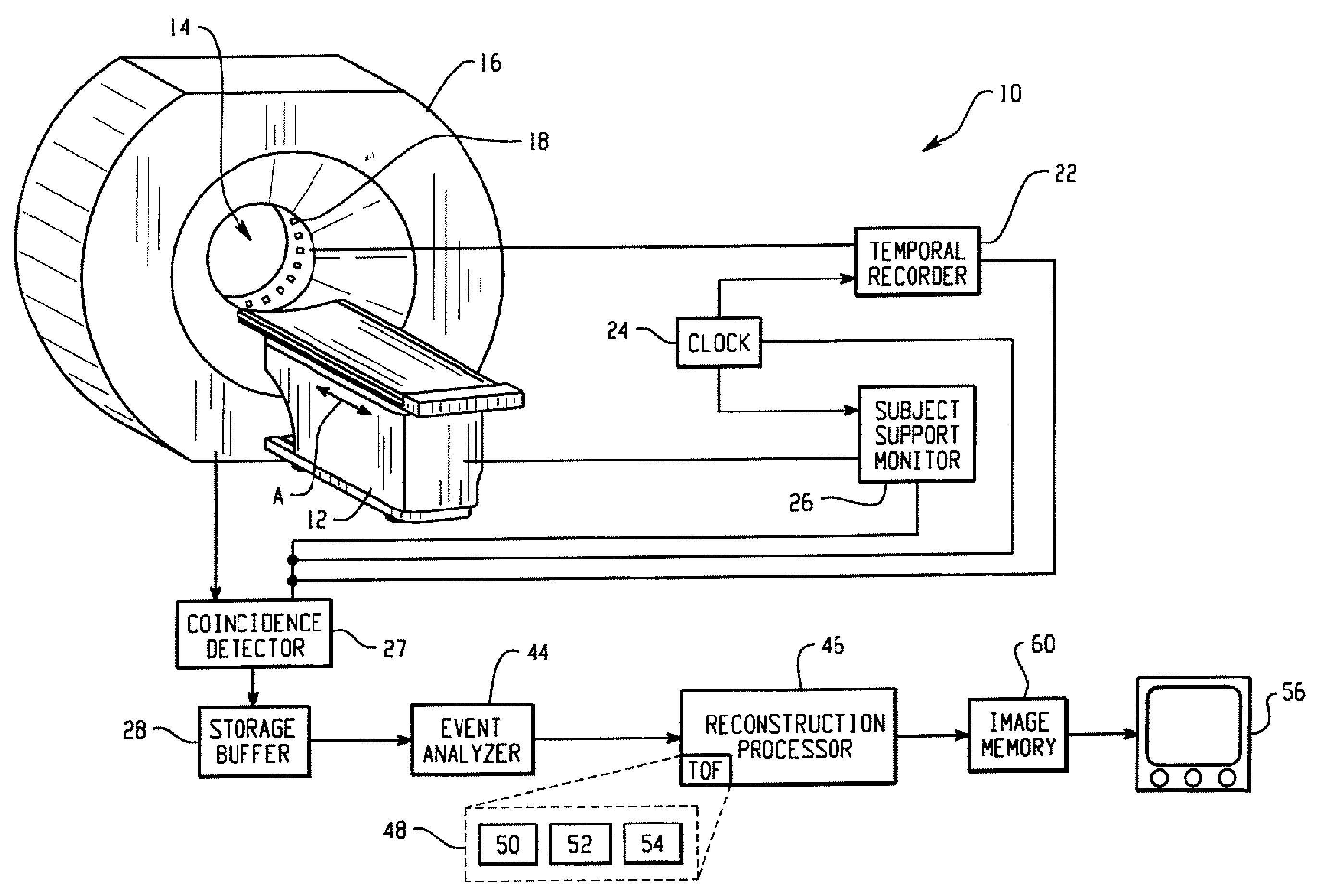
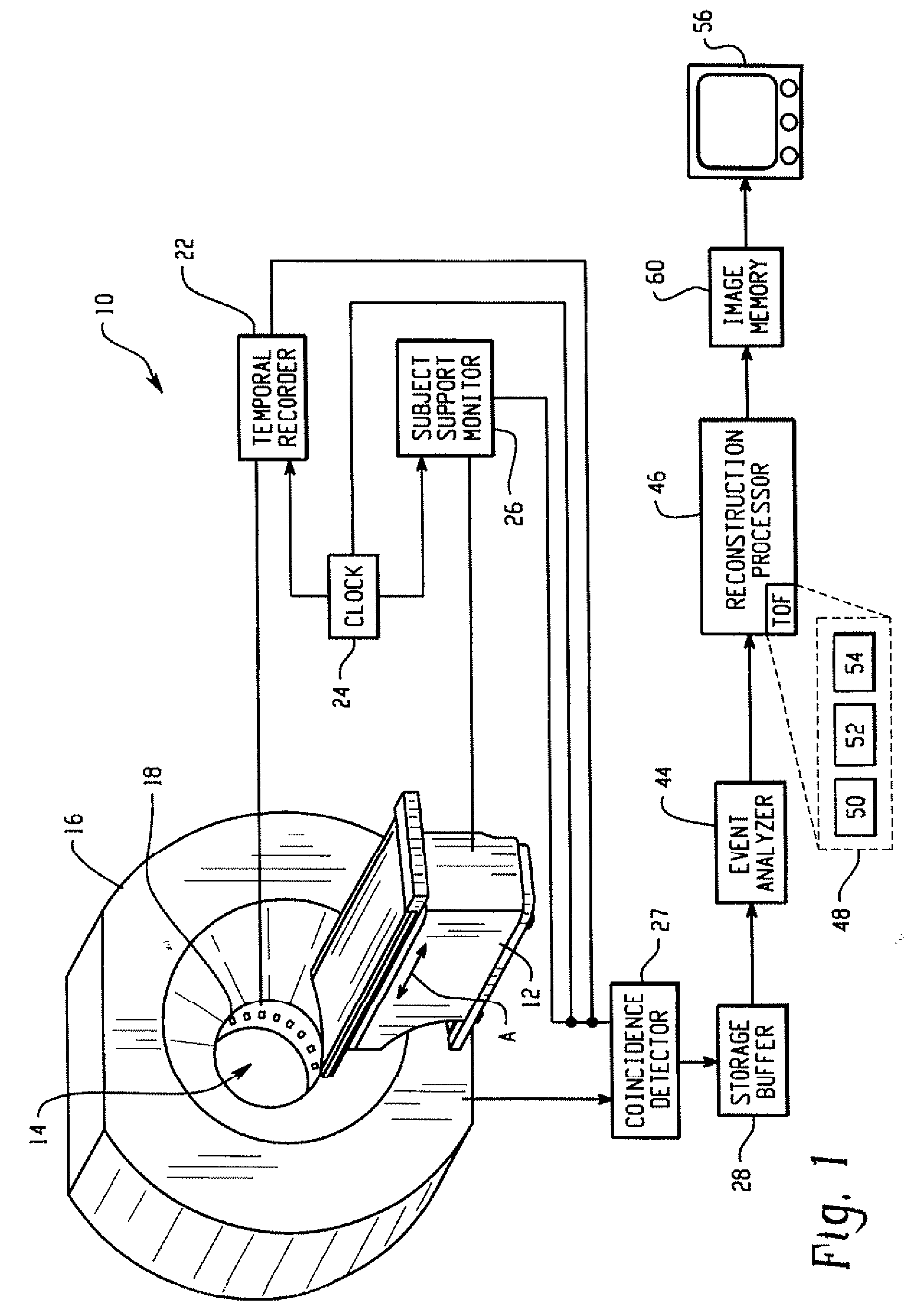
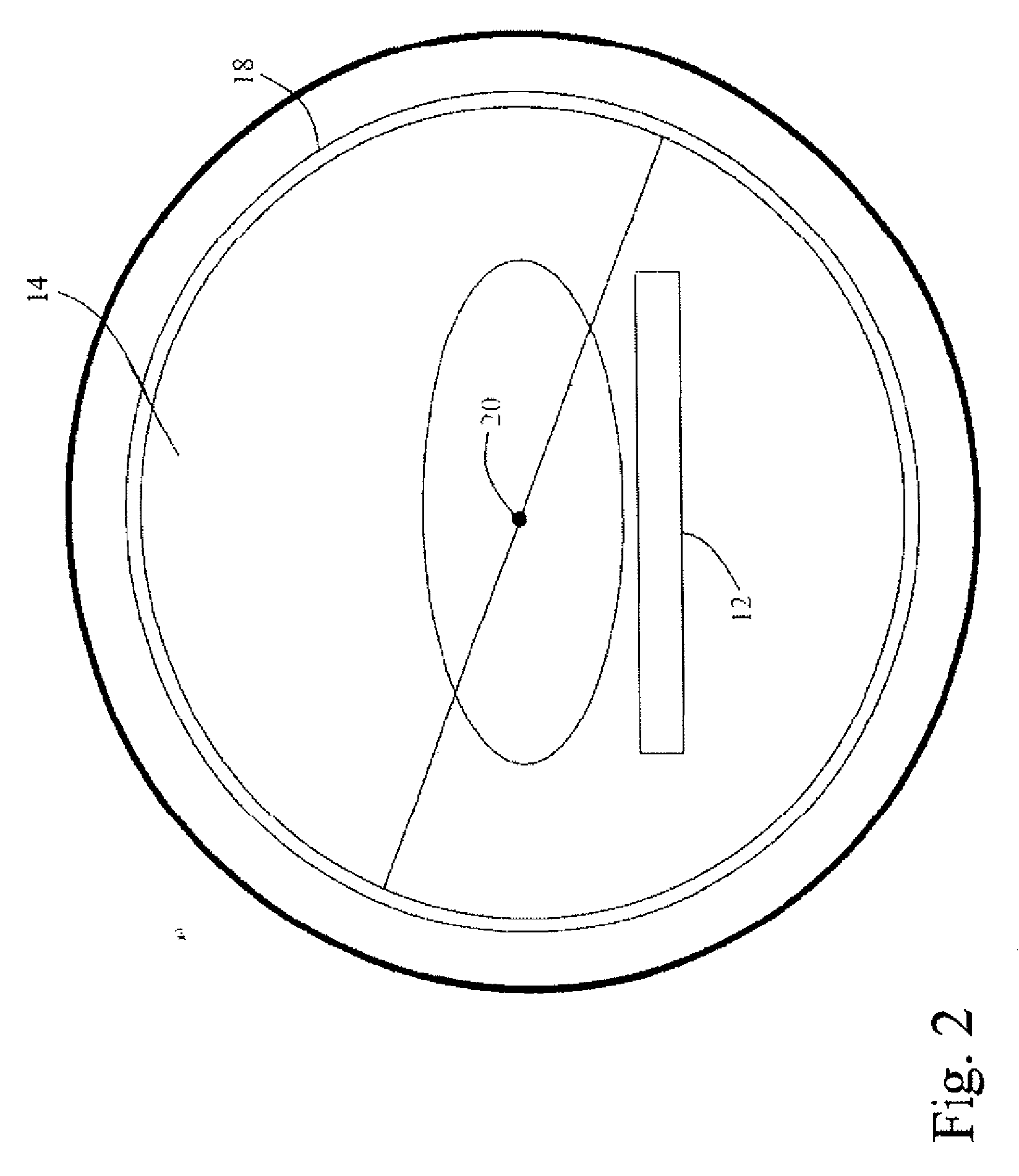
[0016] With reference to FIG. 1, a preferred embodiment of a nuclear medicine scanner 10 is shown. Prior to a scan, a subject is placed on a subject support surface 12. The subject support surface of moves along its longitudinal axis A, into and out of a bore 14 of a gantry 16 of the scanner 10. The bore of a PET scanner is lined with a cylinder of radiation detectors 18. Optionally, the detectors include a plurality of detector heads. In either ease, the detectors 18 are disposed around and along the subject receiving bore 14 to receive nearly concurrently incident γ-rays. Typically, incident γ-rays strike the detectors 18 which preferably include an array of scintillation crystals and photodetectors, although solid state, Anger-type, and other detectors are contemplated. The scintillation crystals emit small bursts of visible light when they are struck with γ-rays, and the visible light is detected by the photodetectors and converted into electrical signals. Solid state detectors,...


PUM


Abstract

In positron emission tomography, a nuclear medicine scanner is utilized to detect γ-ray events resulting from positron annihilation events. Molecules with known behaviors are tagged with radioactive isotopes which decay into γ-ray pairs which are detected coincidentally, i.e. in a near-simultaneous fashion, by radiation detectors. A temporal recorder and a subject support monitor indicate the time and position of the subject when the coincident γ-rays were detected. A storage buffer collects γ-ray detection times and locations along with support positions. Every 1 / 100th- 1 / 10th second, a batch of data collected in the buffer is reconstructed into overlapping portions of an image memory as the support moves continuously through the scanner.

Description

CROSS REFERENCE TO RELATED APPLICATIONS [0001] This application is a Continuation of PCT application number PCT / IB2005 / 054116 filed Dec. 9, 2005 which claims the benefit of U.S. provisional application Ser. No. 60 / 638,915 filed Dec. 22, 2004, both of which are incorporated herein by reference.BACKGROUND OF THE INVENTION [0002] The present invention relates to the field of medical imaging. It finds particular application to the acquisition of time of flight (TOF) positron emission tomography (PET) scans, and will be described with particular reference thereto. The invention is also applicable to single photon emission computed tomography (SPECT), and PET as well as other imaging modalities. [0003] Typically, in nuclear imaging, a subject is imaged in axial slices that combine to form a 3D representation of a region of interest. This region could be localized, such as the brain or heart, but it is also typical to perform full body PET scans. Some PET scanners utilize a step and shoot ...

Claims


Application Information

Patent Timeline
Patent Type & Authority Applications(United States)
IPC IPC(8): G01T1/161G01T1/164
CPCG01T1/1642A61B6/037G01T1/2985
Inventor MUEHLLEHNER, GERDPARMA, MICHAEL J.
Owner KONINKLIJKE PHILIPS ELECTRONICS NV
Why Eureka
Try Eureka