Ferrite sintered magnet

a sintered ferrite magnet, high-performance technology, applied in the direction of ferroso-ferric oxides, magnets, iron compounds, etc., can solve the problems of failing to meet the above requirement of thinning, failing to sufficiently meet the requirement of thinning, and poor magnetic properties of sintered ferrite magnets, etc., to achieve high residual magnetic flux density br, high intrinsic coercivity, and high squareness ratio hk/hcj

Active Publication Date: 2006-12-21
HITACHI METALS LTD
View PDF4 Cites 33 Cited by
  • Summary
  • Abstract
  • Description
  • Claims
  • Application Information

AI Technical Summary

Benefits of technology

[0009] Accordingly, an object of the present invention is to provide a high-performance sintered ferrite magnet having a high residual magnetic flux density Br, and a high intrinsic coercivity Hcj that does not decrease even if it is made thinner, and further has a high squareness ratio Hk / Hcj, if necessary.

Problems solved by technology

Sintered ferrite magnets obtained by this method, however, fail to sufficiently meet the requirement of thinning, needing further improvement in magnetic properties, as is clear from Sample Nos. 1 and 2.
This sintered ferrite magnet, however, has as low Hk / Hcj as 75.9-80.6% (see Sample Nos. 21-23), failing to meet the above requirement of thinning.
However, this sintered ferrite magnet has poor magnetic properties because of having both the M-type ferrite phase and the spinel ferrite phase.

Method used


Image

  • Ferrite sintered magnet
  • Ferrite sintered magnet
  • Ferrite sintered magnet

Examples


example 1

CONVENTIONAL EXAMPLE 1

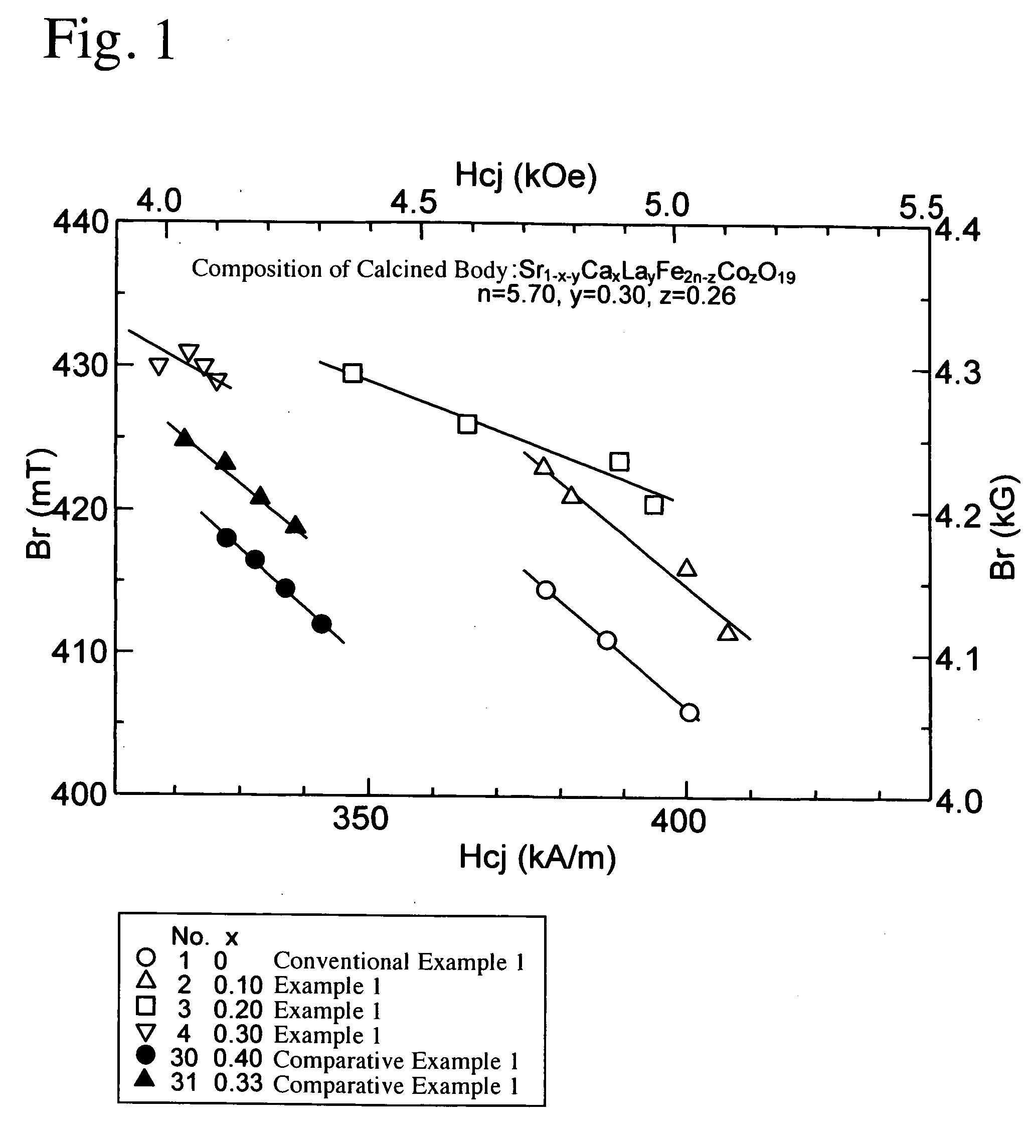
[0119] The same SrCO3 powder, CaCO3 powder, La(OH)3 powder, α-Fe2O3 powder and Co3O4 powder as in Example 1 were mixed to a basic composition of Sr1−x−yCaxLayFe2n−zCOzO19 (n=5.7, y=0.3, z=0.26, and x=0). Subsequently, calcining, pulverizing, and molding and sintering in a magnetic field were conducted in the same manner as in Example 1, and the resultant sintered body was measured with respect to magnetic properties at room temperature. The results are shown in FIG. 1 (white circle: x=0). The basic compositions of the calcined body and the sintered body are shown in the row of Sample No. 1 in Tables 1 and 2.

example 2

CONVENTIONAL EXAMPLE 2

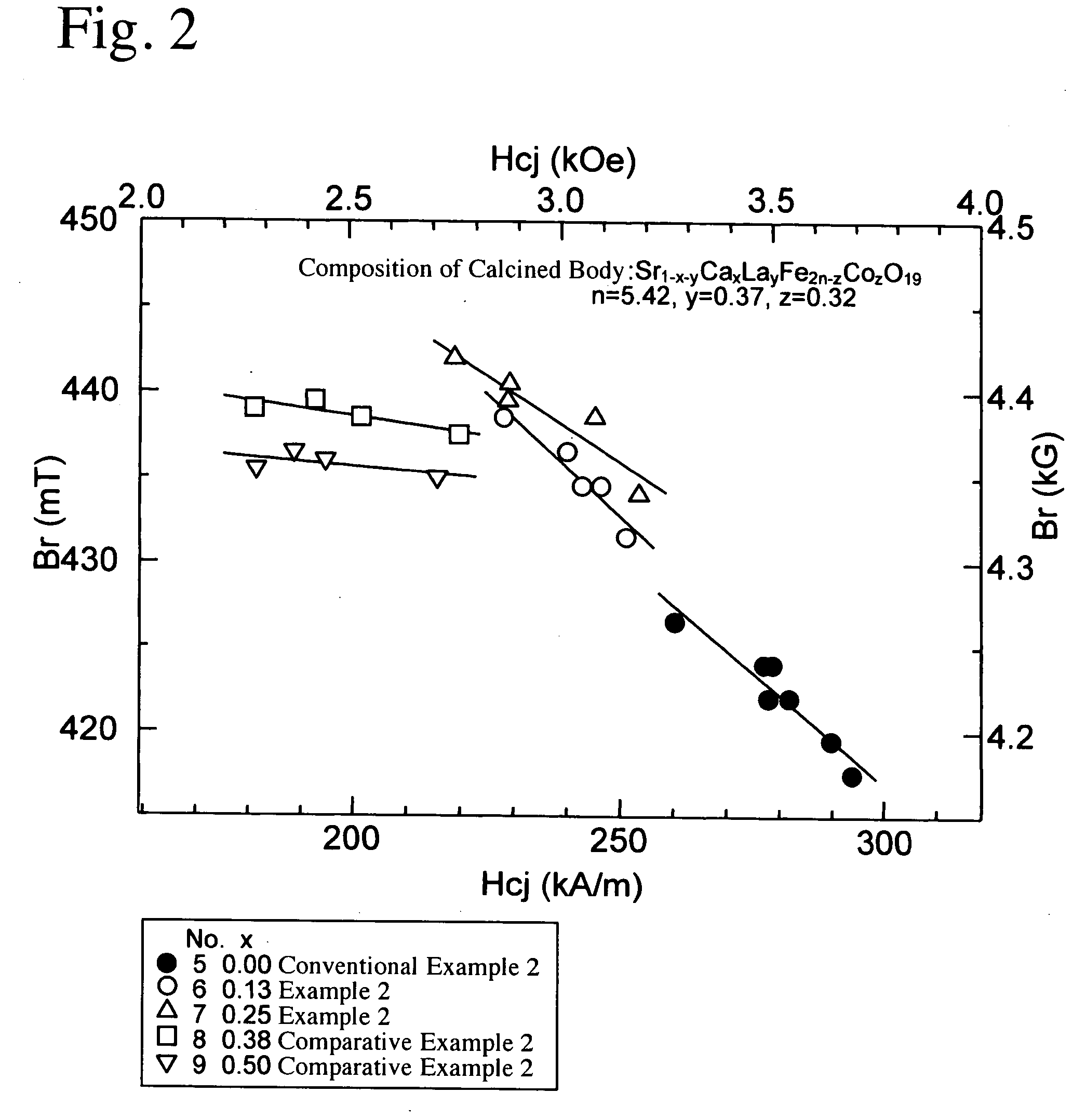
[0124] Calcining, dry coarse pulverization, wet fine pulverization, and molding and sintering in a magnetic field were conducted in the same manner as in Example 2, except for changing the basic composition of a calcined body to that of Sample No. 5 shown in Table 3 (the amount (x) of Ca prior-added 0). The resultant anisotropic sintered ferrite magnet was measured with respect to magnetic properties at room temperature. The results are shown in FIG. 2. The basic compositions of the calcined body and the sintered body are shown in Tables 3 and 4.

example 3

CONVENTIONAL EXAMPLE 3

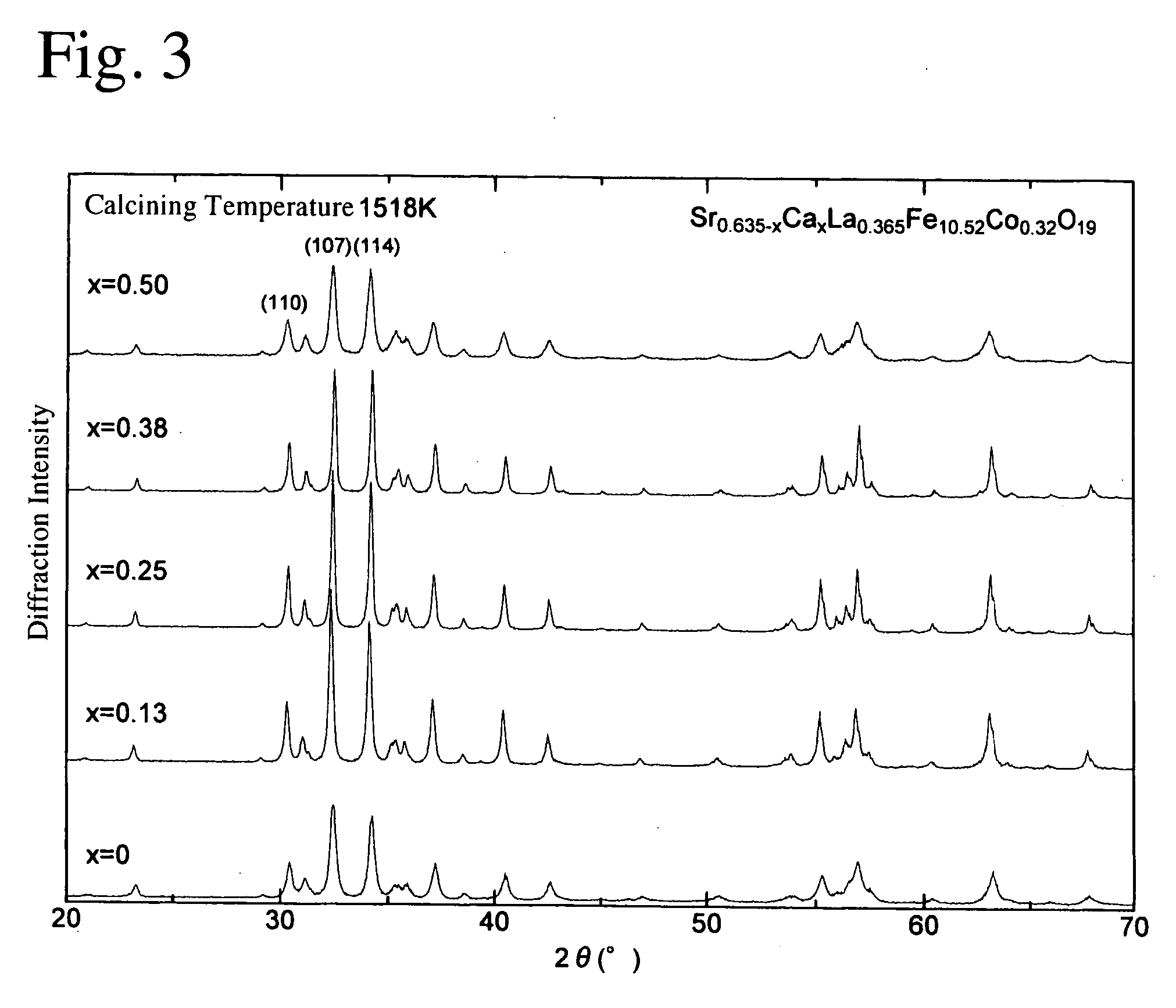
[0130] A calcined body was produced in the same manner as in Example 3, except for using the basic composition shown in the row of Sample No. 65 in Table 5 (the amount (x) of Ca prior-added=0), and subjected to X-ray diffraction measurement. The results are shown in FIGS. 3-6.

[0131] The calcined body was subsequently subjected to dry coarse pulverization, wet fine pulverization, and molding and sintering in a magnetic field in the same manner as in Example 3. The measurement of the magnetic properties of the resultant anisotropic sintered ferrite magnet at room temperature indicates that its Br and Hcj were lower than those of Example 3. The basic compositions of the calcined body and the sintered body are shown in the row of Sample No. 65 in Tables 5 and 6.


PUM

PropertyMeasurementUnit
diameteraaaaaaaaaa
diameteraaaaaaaaaa
diameteraaaaaaaaaa

Abstract

A sintered ferrite magnet having a basic composition represented by the general formula: A1−x−y+aCax+bRy+cFe2n−zCoz+dO19 (atomic ratio), wherein a, b, c and d represent the amounts of an A element, Ca, an R element and Co added in the pulverization step of an oxide magnet material, which are numerals meeting the conditions of 0.03≦x≦0.4, 0.1≦y≦0.6, 0≦z≦0.4, 4≦n≦10, x+y≦1, 0.03≦x+b≦0.4, 0.1≦y+c≦0.6, 0.1≦z+d≦0.4, 0.50≦[(1−x−y+a)/(1−y+a+b)]≦0.97, 1.1≦(y+c)/(z+d)≦1.8, 1.0≦(y+c)/x≦20, and 0.1≦x/(z+d)≦1.2.

Description

FIELD OF THE INVENTION [0001] The present invention relates to a high-performance sintered ferrite magnet having higher intrinsic coercivity Hcj and residual magnetic flux density Br than those of conventional sintered ferrite magnets, which is extremely suitable for a wide range of applied magnet products, such as motors for automobiles or electric appliances, magnet rolls for copiers, etc. BACKGROUND OF THE INVENTION [0002] Sintered ferrite magnets having magnetoplumbite-type (M-type) structures are used in various applications including motors, rotors of electric generators, etc. Sintered ferrite magnets having higher magnetic properties are recently required for the purpose of reduction in size and weight of motors for automobiles and increase in efficiency of motors for electric appliances. Sintered ferrite magnets used in motors for automobiles, for instance, are required to be thin for the purpose of reduction in size and weight. That is, demand is mounting for sintered ferri...

Claims


Application Information

Patent Timeline
Patent Type & Authority Applications(United States)
IPC IPC(8): H01F1/00C04B35/26H01F1/11
CPCC04B2235/767H01F1/11H01F41/0266C04B35/2633C04B35/63C04B2235/3208C04B2235/72C04B2235/3224C04B2235/3227C04B2235/3229C04B2235/3272C04B2235/3277C04B2235/3418C04B2235/3213
Inventor TAKAMI, TAKASHIOGATA, YASUNOBU
Owner HITACHI METALS LTD
Why Eureka
Try Eureka