
Heat spreader for use with light emitting diode

a technology of light-emitting diodes and heat-spreading devices, which is applied in the direction of printed circuit aspects, transportation and packaging, chemical instruments and processes, etc., can solve the problems of reducing the use value of heat sink materials such as copper and aluminum, and reducing the efficiency of heat transfer, so as to achieve high thermal conductivity materials and increase tensile strength

Inactive Publication Date: 2006-12-21
HCC AEGIS
View PDF6 Cites 7 Cited by
  • Summary
  • Abstract
  • Description
  • Claims
  • Application Information

AI Technical Summary

Benefits of technology

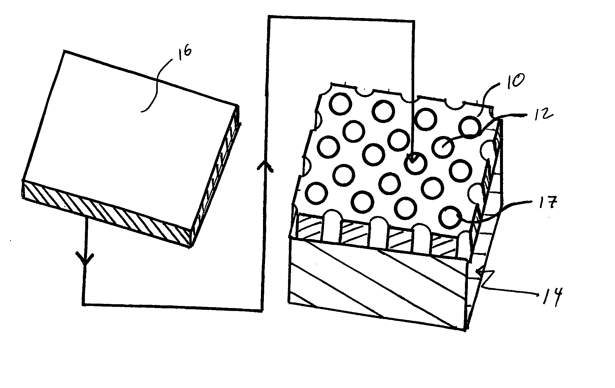
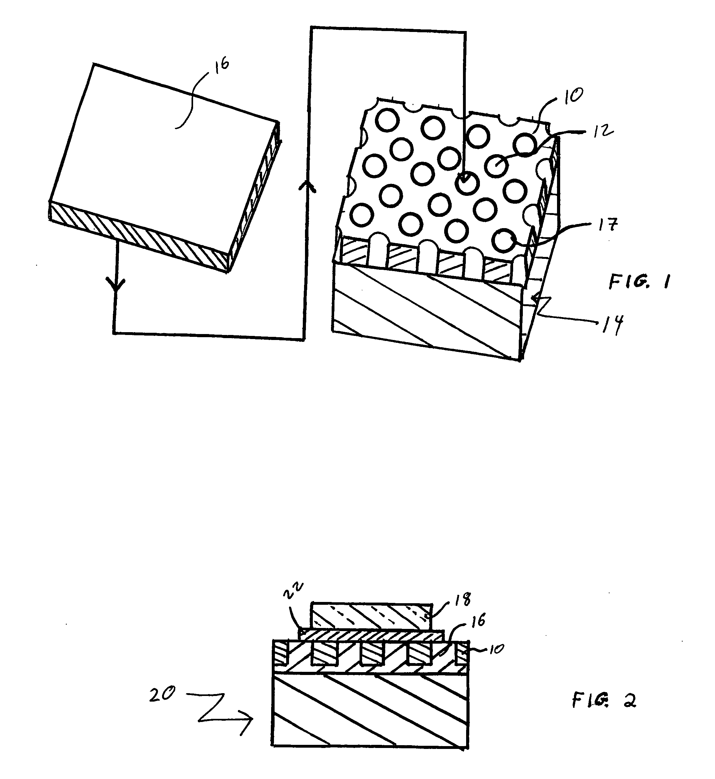
[0012] In accordance with a second embodiment of the invention, there is provided a method for the manufacture of a composite heat spreader which includes providing a low coefficient of thermal expansion material having opposing first and second surfaces with an array of through holes extending from said first surface to said second surface, disposing a high thermal conductivity substrate adjacent to the second surface and a wettable material adjacent to the first surface and then heating to a temperature effective to cause the wettable material to melt thereby bonding the second surface to the high thermal conductivity substrate and further to substantially fill the array of through holes.
[0014] It is another feature of the invention, that the high thermal conductivity material may be selected to be a work hardenable copper alloy. In this instance, the composite heat spreader may be worked after the heating step of the second embodiment to increase tensile strength.

Problems solved by technology

Therefore, traditional heat sink material such as copper and aluminum having relatively high coefficients of thermal expansion are not be used.
However, the intervening molybdenum layer, while effective to reduce the coefficient of thermal expansion the composite, reduces the effectiveness of the transfer of heat.
Air is an effective thermal insulator and gaps between the lattice and the copper inserts could cause hot spots which potentially could damage the LED device.
However, it is difficult to achieve complete filling of the entire array of holes and there remains a possibility of air gaps.
Further, distortion of the array of holes is possible when compressed between rolling mill rollers.

Method used


Image

  • Heat spreader for use with light emitting diode
  • Heat spreader for use with light emitting diode

Examples


Embodiment Construction

[0019] With reference to FIG. 1, a relatively low coefficient of thermal expansion material 10, such as an iron / nickel-base alloy, is provided with an array of through holes 12. By relatively low CTE material, it is meant that the material has a coefficient of thermal expansion of less than 7 parts per million per degree centigrade (7 ppm / ° C.) over the temperature range of room temperature (nominally 22° C.) to 350° C. Suitable materials, having nominal compositions specified in weight percent, include the material sold under the trademark KOVAR, which is 29% nickel-17% cobalt-balance iron; the material sold under the trademark INVAR, which is 36% nickel-balance iron; and the material sold under the trademark ALLOY 42, which is 42% nickel-balance iron.

[0020] The through holes 12 are formed by any suitable process such as photolithography and occupy a minimum of 50% of the surface area of the low CTE material. More preferably, from 75 to 90% of the surface area of the low CTE mater...


PUM

PropertyMeasurementUnit
Temperatureaaaaaaaaaa
Fractionaaaaaaaaaa

Abstract

A substrate for an integrated circuit device includes a low coefficient of thermal expansion material having opposing first and second surfaces with an array of through holes extending from the first surface to the second surface. A high thermal conductivity substrate is adjacent to the second surface of the low coefficient of thermal expansion material and a wettable material bonds the low coefficient of thermal expansion material to the high thermal conductivity substrate while also substantially filling said array of through holes. An integrated circuit device, such as a light emitting diode, may be bonded to the first surface of the low coefficient of thermal expansion material by a compliant die attach material.

Description

CROSS REFERENCE TO RELATED APPLICATION(S) [0001] This application claims the benefit of U.S. Provisional Application No. 60 / 661,524, filed Mar. 14, 2005.BACKGROUND OF THE INVENTION [0002] 1. Field of the Invention [0003] This invention relates to composite heat spreaders, and more particularly to heat spreaders having an iron-nickel-base alloy component and a copper-base alloy component. The composite heat spreader has a coefficient of thermal expansion (CTE) and a thermal conductivity effective for mounting a light emitting diode (LED). [0004] 2. Description of the Related Art [0005] Solid state lighting, such as light emitting diodes, has many advantages over traditional light sources such as incandescent and florescent. Such advantages include longer life and higher efficiency. Unlike traditional light sources that dissipate energy lost as heat in the radiant beam of light, the heat energy developed during operation of an LED does not radiate away from the LED in the light beam a...

Claims


Application Information

Patent Timeline
IPC IPC(8): B32B3/00H05K1/00
CPCH01L33/641H05K1/0203H05K1/056Y10T428/24917H05K2201/068H05K2201/09681H05K2201/10106H05K3/202
Inventor TOWER, STEVEN A.
Owner HCC AEGIS
Learn More