Resin-coated micron conductive fiber wiring

a technology of conductive fibers and conductive fibers, applied in the direction of insulated conductors, cables, conductors, etc., can solve the problems of metal-based elements, resistive heating elements currently used in the art have disadvantages, and lose density such as it rises, and achieves high conductive material performance and low cost

Inactive Publication Date: 2006-12-28
AISENBREY THOMAS
View PDF6 Cites 34 Cited by
  • Summary
  • Abstract
  • Description
  • Claims
  • Application Information

AI Technical Summary

Benefits of technology

[0010] A principal object of the present invention is to provide a low cost and highly effective conductive material.

Problems solved by technology

Water at the bottom of the pan is superheated causing it to lose density such that it rises.
However, resistive heating elements currently used in the art have disadvantages.
Metal-based elements, and particularly nichrome and tungsten, can be brittle and therefore not suitable for applications requiring a flexible heating element.
Further, the large thermal cycles inherent in many product applications and the brittleness of these materials will cause thermal fatigue.
However, if the application requires the resistive element to change or flex positions, then the resistive element will tend to wear out due to metal fatigue.
These elements are expensive, can require very high temperature processing, and are limited in shape.
In addition, when a breakage occurs, typically due to fatigue as described above, then the entire element stops working and must be replaced.

Method used


Image

  • Resin-coated micron conductive fiber wiring
  • Resin-coated micron conductive fiber wiring
  • Resin-coated micron conductive fiber wiring

Examples


embodiment 500

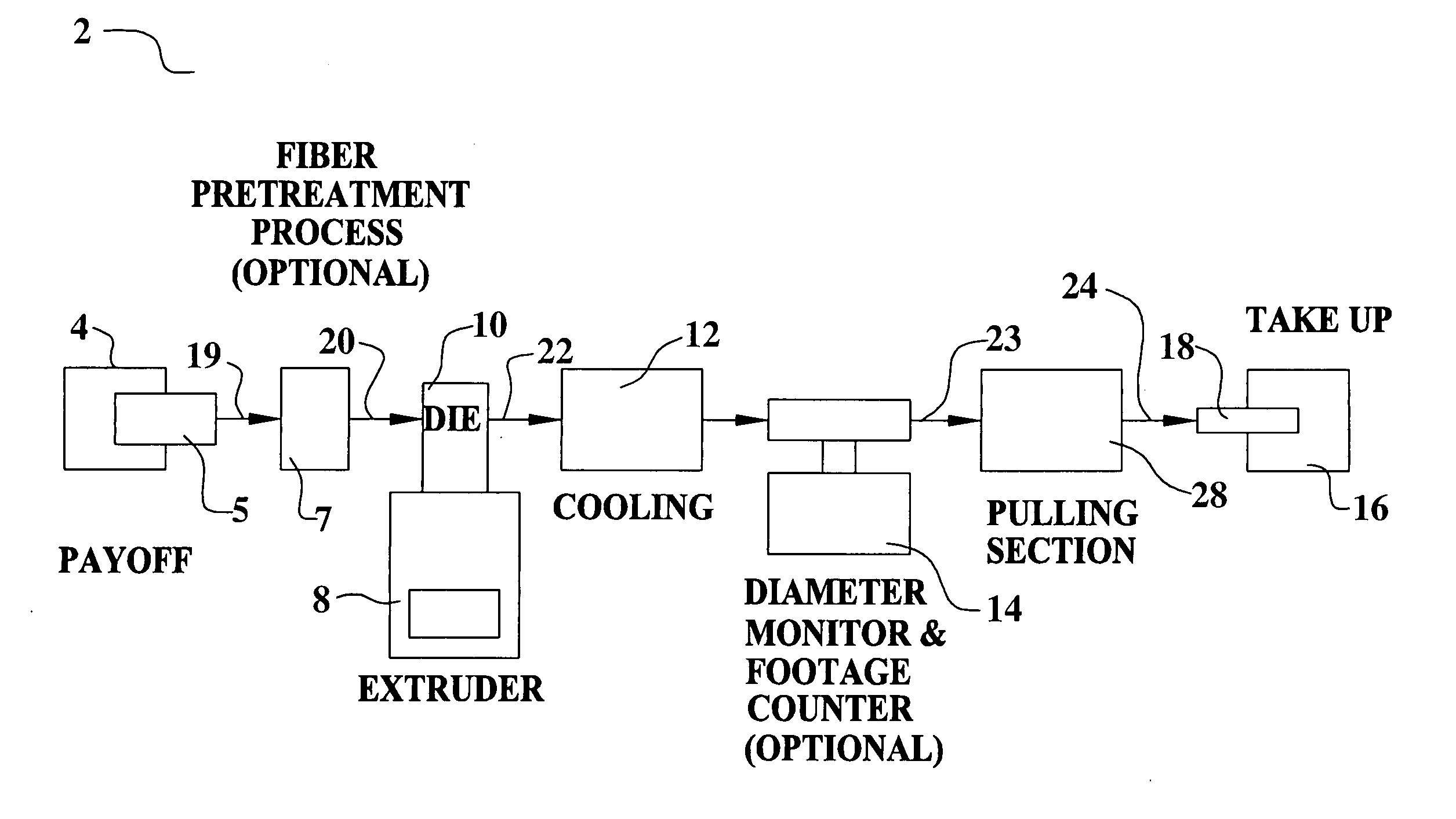
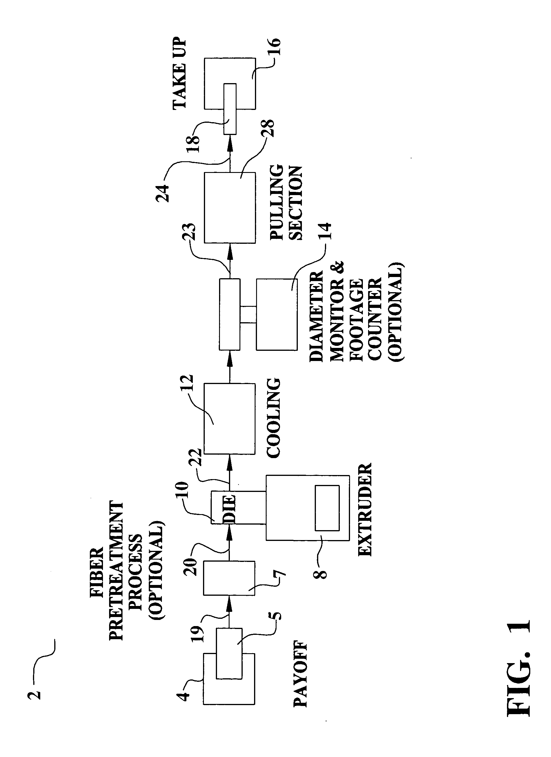
[0076] Referring now to FIG. 10, an embodiment 500 of the present invention is illustrated. An antenna 520 for a transceiver device 510 is formed from resin-coated, micron conductive fiber wiring 520 is shown. A transceiver device, such as a cellular or mobile telephone, a wireless computer, a walkie-talkie, or the like, requires an antenna structure to transmit and receive signals by electromagnetic energy. In addition, receiver devices, such as radios or televisions, or transmitting devices, such as beacons, require antenna structures. The resin-coated, micron conductive fiber wiring 520 of the present invention can be formed into the required antenna 520 shapes and / or sizes to create the desired resonance frequency characteristics. The resin-coated, micron conductive fiber wiring 520 demonstrates excellent absorption and / or transmission of RF energy. The low resistivity of the resin-coated, micron conductive fiber wiring 520 provides substantially excellent performance.

[0077] In ...

embodiment 550

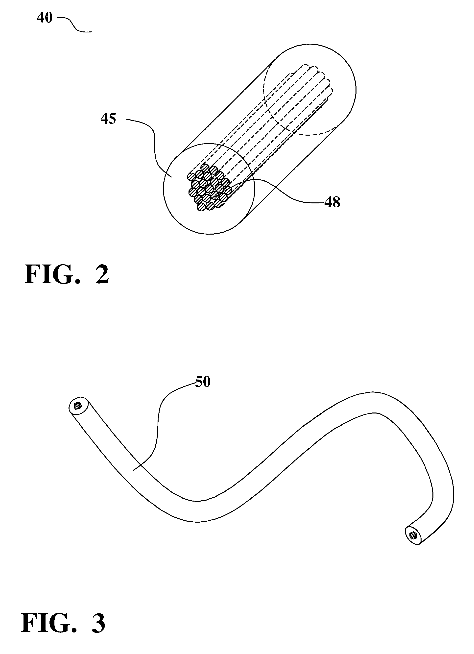
[0078] Referring now to FIG. 11, an embodiment 550 of the present invention is illustrated. The resin-coated, micron conductive fiber wiring 560 is applied to a high voltage power line system 550. In a high voltage power line system 550, large cables 560 are suspended high above the ground via towers 570. The electrical power is typically transmitted at a large voltage such that the current loading in the wiring 560 is reduced and the electrical loss due to I 2R is reduced. The resin-coated, micron conductive fiber wiring 560 presents several advantages in this application. First, the micron fiber is lower in weight than copper or aluminum cabling and yet is capable of low resistance. As a result, the weight loading on the towers 570 is reduced. In addition, the resin-coated, micron conductive fiber wiring 560 can be made substantially stronger by winding fiber bundles around a center core as is shown in FIG. 12 and is described below. For example, a center core of glass fiber or of...

embodiment 800

[0083] Referring now to FIG. 16, an embodiment 800 of the present invention is illustrated. Several alternative cross sectional shapes of resin-coated, micron conductive fiber wiring are shown. In one embodiment, a rectangular array 810 of fiber is surrounded with a resin-based coating 820 to make a rectangular cross section. In another embodiment, a star array 830 of fiber is surrounded with a resin-based coating 840 to form a star cross section. In another embodiment, a corrugated cross section of resin-based coating 860 is formed around an array 850 of fiber.


PUM

PropertyMeasurementUnit
diameteraaaaaaaaaa
diameteraaaaaaaaaa
thicknessaaaaaaaaaa

Abstract

A resin-coated, micron conductive fiber wiring material, a method of fabricating, and applications are achieved. The micron conductive fibers may be metal fiber or metal plated fiber. Further, the metal plated fiber may be formed by plating metal onto a metal fiber or by plating metal onto a non-metal fiber. Any platable fiber may be used as the core for a non-metal fiber. Superconductor metals may also be used as micron conductive fibers and/or as metal plating onto fibers in the present invention.

Description

RELATED PATENT APPLICATIONS [0001] This Patent Application claims priority to the U.S. Provisional Patent Application 60 / 687,613, filed on Jun. 3, 2005, which is herein incorporated by reference in its entirety.BACKGROUND OF THE INVENTION [0002] (1) Field of the Invention [0003] This invention relates to resin-coated, micron conductive fiber wiring including methods of manufacture and applications. [0004] (2) Description of the Prior Art [0005] From common kitchen appliances to sophisticated temperature control devices for scientific application, resistive heating elements are ubiquitous in application. Most heating elements are highly resistive metal wire, such as nickel-chromium (nichrome) or tungsten, designed to provide the necessary resistance for the heating required. The resistance of the heating element is determined by the resistivity of the wire, its cross-sectional area, and its length. The heat generated by the heating element is determined by the current passing through...

Claims


Application Information

Patent Timeline
Patent Type & Authority Applications(United States)
IPC IPC(8): H01B11/06
CPCH05B3/56H05B3/12B29C48/154B29C48/34B29C48/91
Inventor AISENBREY, THOMAS
Owner AISENBREY THOMAS
Why Eureka
Try Eureka