
Process for producing three-dimensional shaped article

a three-dimensional model and shaped technology, applied in the direction of additive manufacturing processes, solid and fluid additive manufacturing, electric/magnetic/electromagnetic heating, etc., can solve the problems of time and expense, the method cannot achieve a satisfactory level of properties (texture, color) for a model, and the three-dimensional model for which transparency is required cannot be obtained by the conventional method, etc., to achieve high gloss and transparency, the effect of high modeling speed

Inactive Publication Date: 2006-12-28
FUJIFILM HLDG CORP +1
View PDF8 Cites 26 Cited by
  • Summary
  • Abstract
  • Description
  • Claims
  • Application Information

AI Technical Summary

Benefits of technology

[0011] An object of the present invention is to provide a process for producing a three-dimensional model, the process having high modeling speed and enabling a three-dimensional model having high gloss and transparency to be obtained.
[0012] It is another object of the present invention to provide a three-dimensional modeling technique that enables a target three-dimensional model to be produced faithfully in terms of not only shape but also color. Yet another object of the present invention is to produce a colored three-dimensional model having excellent mechanical strength in a short time and at low cost. Means for Solving the Problems

Problems solved by technology

However, in the present situation the above-mentioned method cannot achieve a satisfactory level of properties (texture, color) for a model when compared with that which is desired.
In particular, it is thought that a three-dimensional model for which transparency is required cannot be obtained by the conventional method because of the difference in properties between the powder and the binder.
Furthermore, in order to impart smoothness to the surface, it is necessary to carry out overcoating and polishing manually, which requires time and expense.
Moreover, it is generally difficult to reliably draw a desired pattern, etc. on a predetermined position of a three-dimensional model by hand painting.
Since a three-dimensional model immediately after forming is shaped only by virtue of the bonding force of the binder, the three-dimensional model has a low strength and, depending on the way it is handled, might be broken.
However, such a step requires time and effort.

Method used


Image

  • Process for producing three-dimensional shaped article
  • Process for producing three-dimensional shaped article
  • Process for producing three-dimensional shaped article

Examples


example 1

[0240] Preparation of UV-Curing Binder ‘Colorless Binder 1’

Polymerizable compound: KAYARAD DPCA605.2gPolymerizable compound: HDDA14.8g(HDDA manufactured by Daicel UCB Co., Ltd.)Photopolymerization initiator: Irgacure 18500.6g

[0241] The above components were stirred and mixed to give colorless transparent binder 1 having a viscosity at 25° C. of about 20 mPa·s.

[0242] Preparation of UV-Curing Binder ‘White Binder 1’

Polymerizable compound: KAYARAD DPCA605.2gPolymerizable compound: HDDA14.8gPhotopolymerization initiator: Irgacure 18500.6gWhite pigment: titanium oxide3g

[0243] The above components were kneaded using a three roll mill to give white binder 1 having a viscosity at 25° C. of about 25 mPa·s.

[0244] Preparation of UV-Curing Binder ‘Yellow Binder 1’

Polymerizable compound: KAYARAD DPCA605.2gPolymerizable compound: HDDA14.8gPhotopolymerization initiator: Irgacure 18500.6gColorant: Y-10.8g

[0245] Y-1 above, and M-1 and C-1 below were as described in the ‘Best Mode for Carrying Out ...

example 2

[0256] A three-dimensional model was formed in the same manner as in Example 1 and evaluated except that as the powder material a phenolic resin was used instead of polymethyl methacrylate.

example 3

[0257] A three-dimensional model was formed in the same manner as in Example 1 and evaluated except that as the powder material polystyrene was used instead of polymethyl methacrylate.


PUM

PropertyMeasurementUnit
Particle sizeaaaaaaaaaa
Thicknessaaaaaaaaaa

Abstract

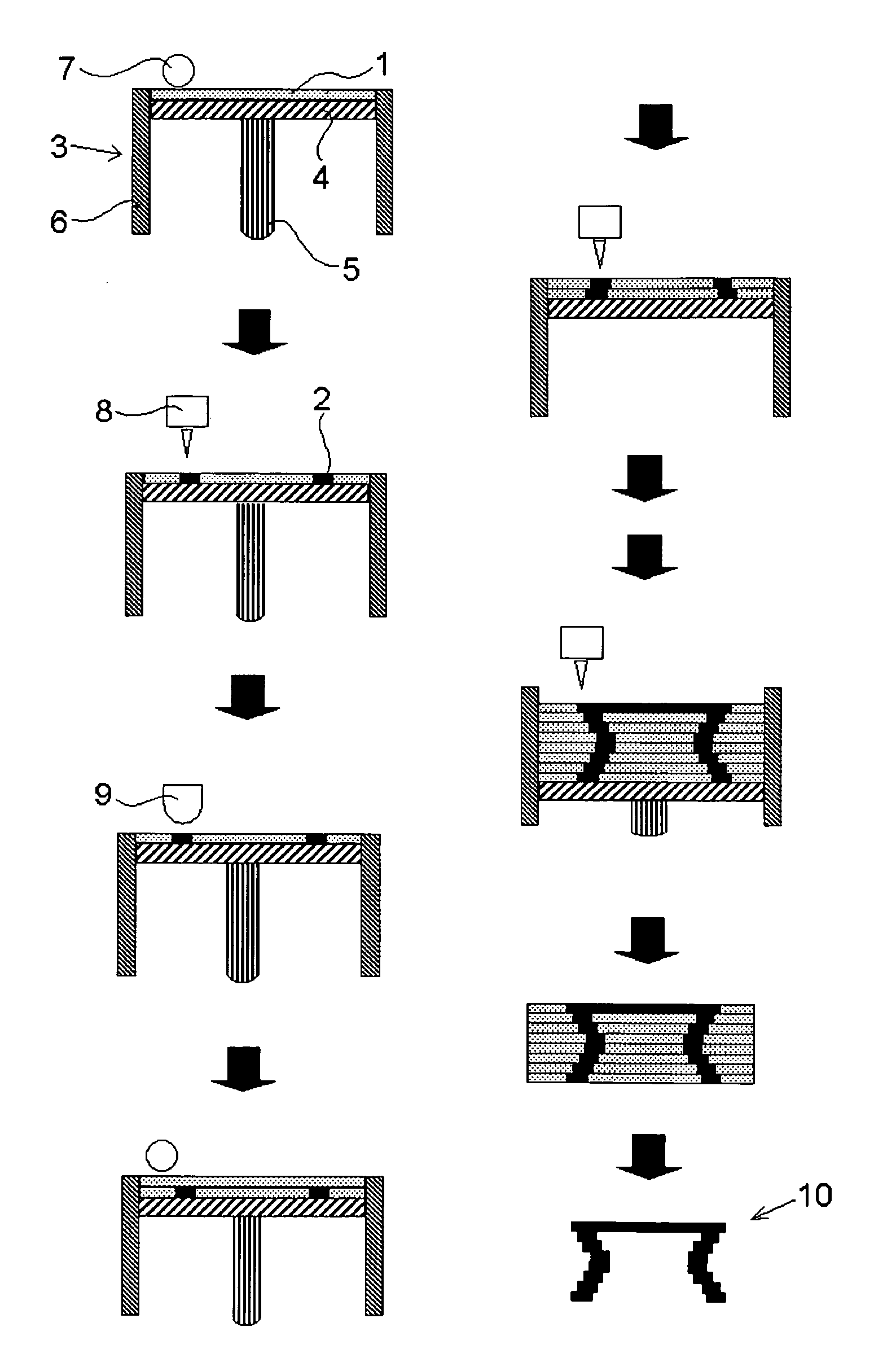
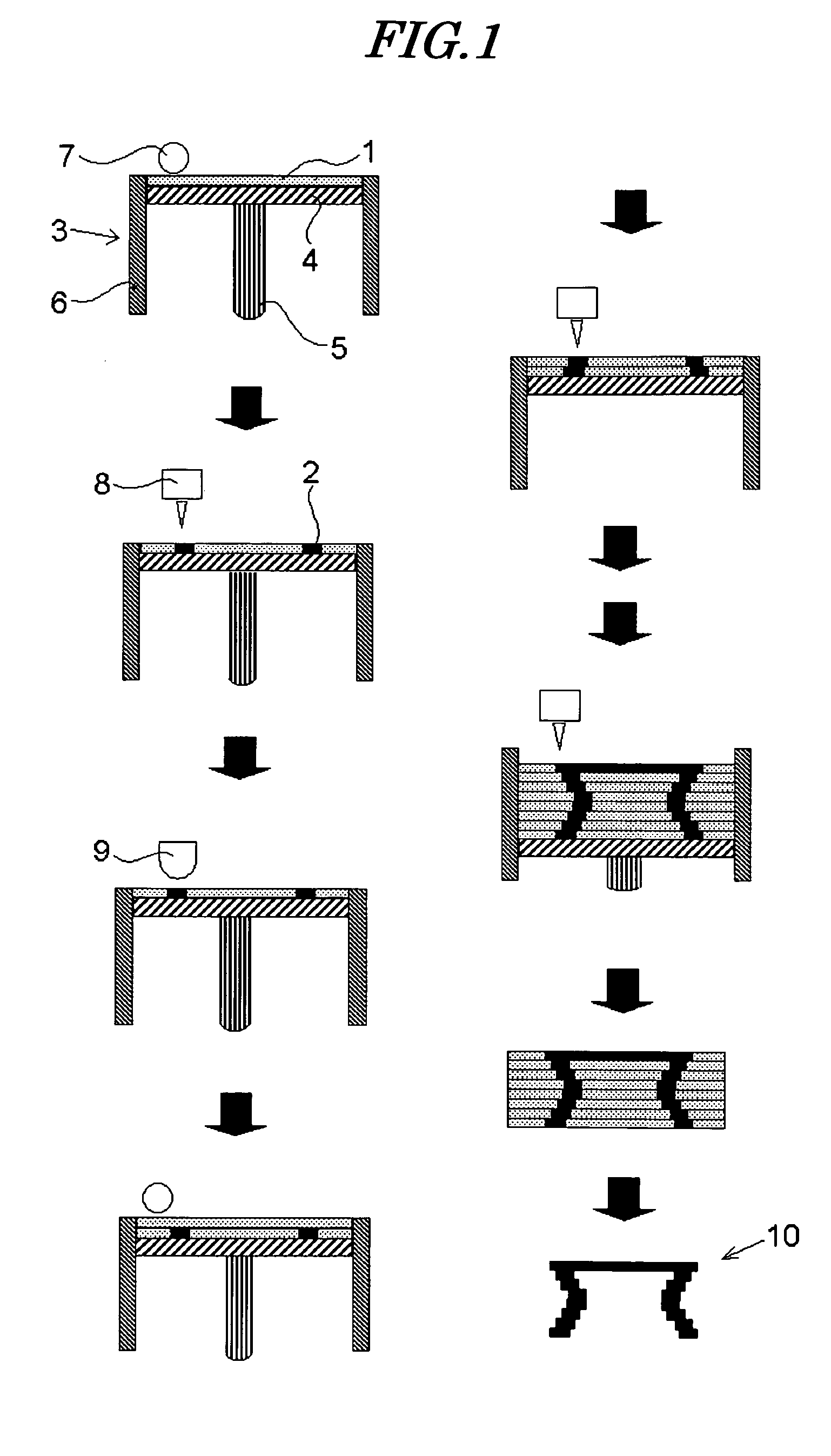
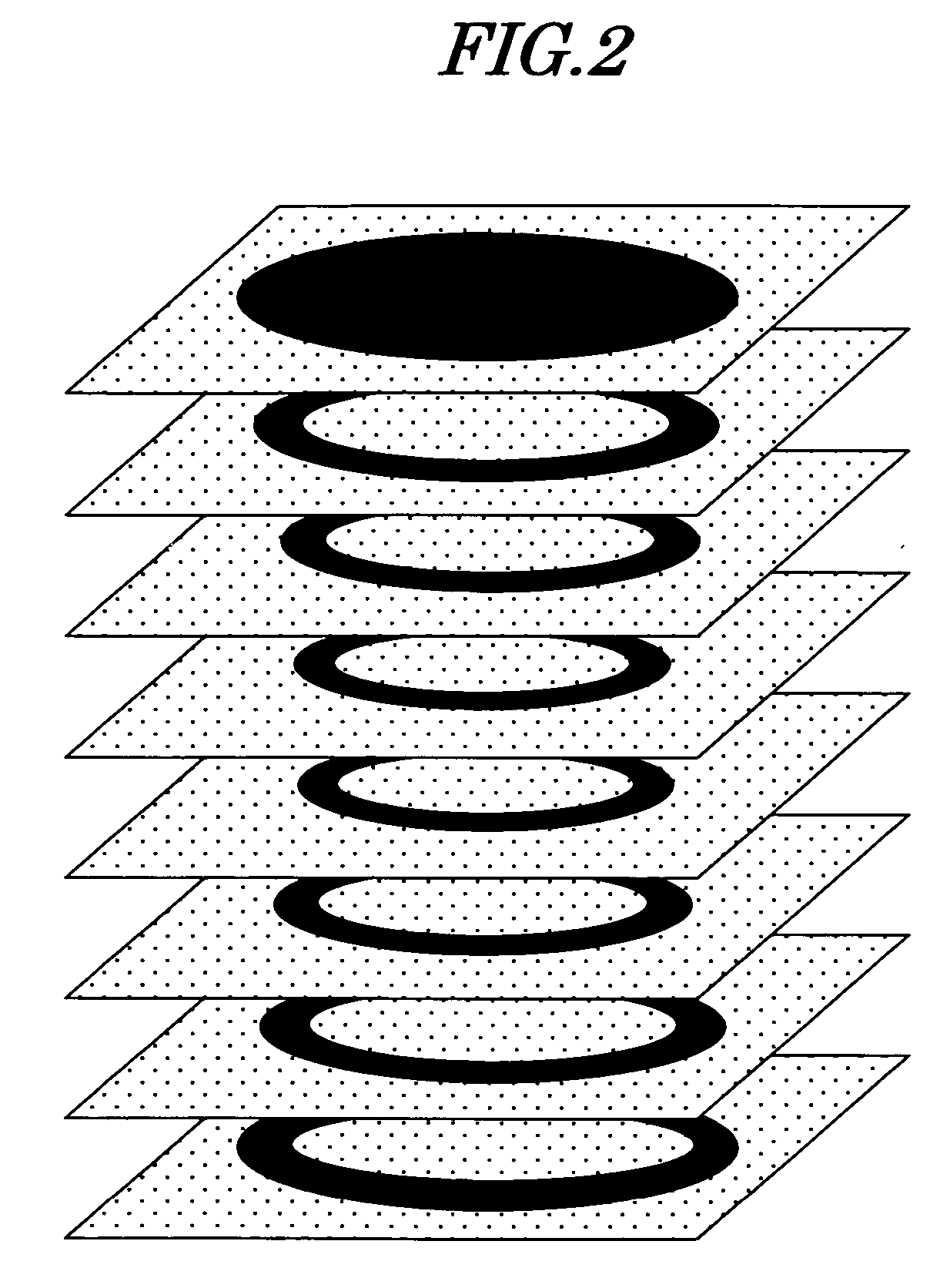
The present invention relates to a process for producing a three-dimensional model, the process having a high modeling speed and enabling a three-dimensional model having high gloss and transparency to be obtained. The process for producing a three-dimensional model is a process for producing a three-dimensional model that includes a step (layer formation step) of forming above a support a layer containing a powder material, and a step (cross-sectional shape formation step) of imagewise bonding the powder material layer by a binder, (a) the powder material employing a synthetic organic powder, and (b) the binder being cured by actinic radiation.

Description

TECHNICAL FIELD [0001] The present invention relates to a process for producing a three-dimensional model and, in particular, to a process for producing a three-dimensional model by sequentially layering a plurality of sliced parallel cross-sectional shapes of a three-dimensional model of an object. BACKGROUND ART [0002] There is a conventionally known technique to form a model, which is a three-dimensional model of a solid modeled object, by bonding with a binder a thin powder layer for each of a plurality of sliced parallel cross-sectional shapes of the modeled object, and sequentially layering these bonded thin cross-sectional shaped layers. [0003] Such a technique is known as rapid prototyping and can be utilized in applications such as component prototyping and design verification. Recently, a system employing an inkjet method, which is inexpensive, fast, and suitable for the formation of a color model, has been proposed and disclosed in, for example, Patent Publication 1. A sp...

Claims


Application Information

Patent Timeline
IPC IPC(8): B29C35/08B29C67/00
CPCB29C67/0081B29C64/165
Inventor SANO, SHOJIRO
Owner FUJIFILM HLDG CORP
Learn More