Method for controlling a handover between two network access devices

a network access device and handover technology, applied in the direction of time-division multiplex, electrical equipment, wireless commuication services, etc., can solve the problems of interference to the reception of mobile-ip advertisements periodically transmitted from foreign agents, data loss and connection interruption, etc., to achieve the effect of accelerating a mobile-ip-based handover

Inactive Publication Date: 2006-12-28
NOKIA SIEMENS NETWORKS GMBH & CO KG
View PDF3 Cites 26 Cited by
  • Summary
  • Abstract
  • Description
  • Claims
  • Application Information

AI Technical Summary

Benefits of technology

[0018] An object of the invention is therefore to provide a method and a subsc

Problems solved by technology

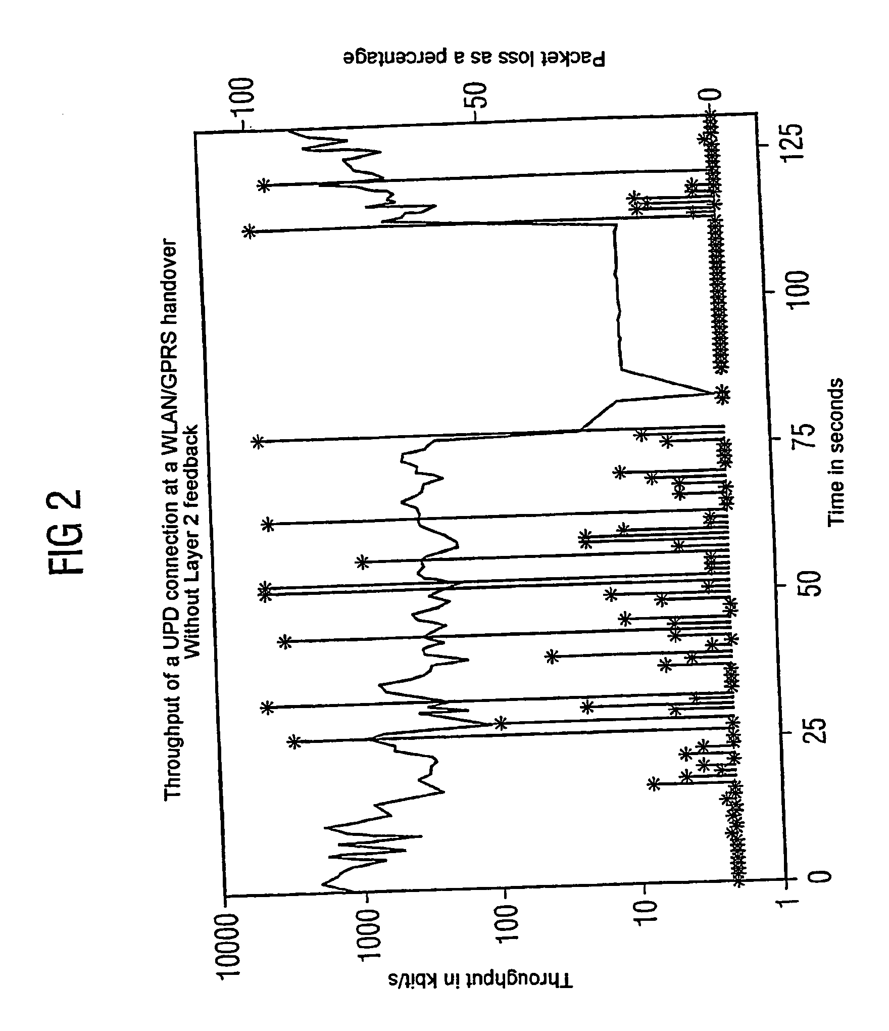
This especially discusses the problem that during a handover between WLAN and cellular mobile systems disadvantageous data losses and connection interruptions can occur due to undefined handovers.
Such losses and interruptions can especially be attributed to situations in which the mobile terminal is in a border area of a WLAN coverage and a handover to a cellular system could be carried out.
In this case, however, for example due to undefined or insufficiently-defined threshold values during the handover controlled by the Mobile-IP protocol, something called a ping-pong effect can occur, with a connection being repeatedly transferred between the two access systems.
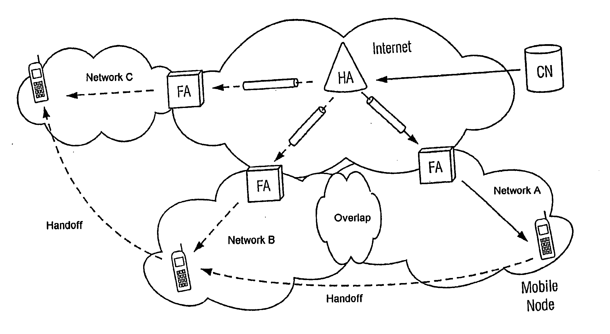
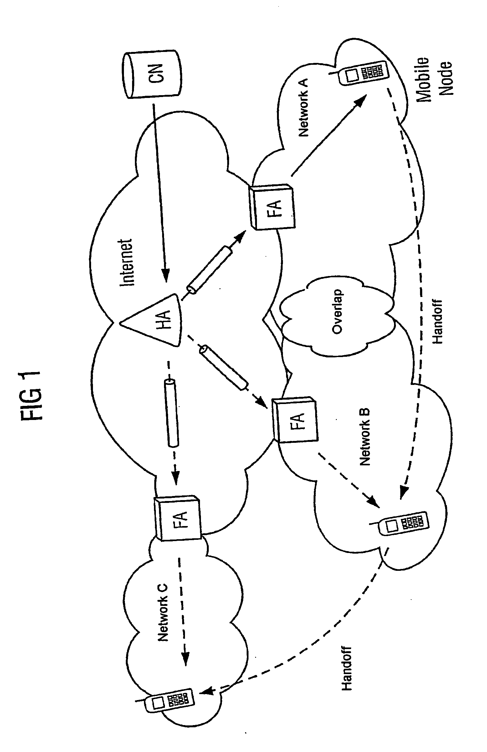
If the mobile terminal moves in the direction of a boundary of the radio coverage area of network A, interference to the reception of the Mobile-IP advertisements periodically transmitted from the foreign agent (FA) of network A occurs due to the deteriorating transmission properties of the radio interface between the access point of network A and the mobile terminal.
If the mobile terminal is in an overlap area of network A and B so that it can also receive signals from a base station of network B, it controls a vertical handover from network A to network B if the handover properties to network B are more favorable than to network A. After a handover has been completed, the mobile terminal henceforth receives the corresponding Mobile-IP advertisements via the foreign agent (FA) of network B. During the handover, the mobile terminal is, however, disadvantageously not in a position to receive data packets from one of the systems participating in the

Method used


Image

  • Method for controlling a handover between two network access devices
  • Method for controlling a handover between two network access devices
  • Method for controlling a handover between two network access devices

Examples


Embodiment Construction

[0033] Reference will now be made in detail to the preferred embodiments of the present invention, examples of which are illustrated in the accompanying drawings, wherein like reference numerals refer to like elements throughout.

[0034] A realization of a method in accordance with the invention in a mobile subscriber terminal is described in the following with reference to FIGS. 3 and 4.

[0035]FIG. 3 shows an example of a known OSI layer model, such as is used in telecommunication engineering for defining different layers. At the lowest layer, called the physical layer, or also layer 1, a transmission of signals takes place via a transmission media, the radio interface is used in the following as the example. The structure of the physical layer is defined relative to the particular standard used, for example in accordance with the named standards WLAN or 802.11, GSM / GPRS, UMTS etc.

[0036] Control of the connection takes place at a higher layer, called the data link layer. This contr...


PUM


Abstract

At least one quality parameter determined in a link layer based on signal transmission to a physical layer mobility-controlling mechanisms of a network layer is used to decide on the transfer in handover between two network access devices. At least one message received by a currently supplying network access device is relayed from the physical layer to the network layer or suppressed according to the at least one quality parameter.

Description

CROSS REFERENCE TO RELATED APPLICATIONS [0001] This application is based on and hereby claims priority to German Application No. 104 55 28.0 filed on Sep. 30, 2003, the contents of which are hereby incorporated by reference. BACKGROUND OF THE INVENTION [0002] 1. Field of the Invention [0003] The invention relates to a method for controlling a handover between two network access devices, especially between two radio communication systems. Furthermore, the invention relates to a subscriber terminal capable of performing a method in accordance with the invention. [0004] 2. Description of the Related Art [0005] In radio communication systems, for example, the European Mobile Radio System of the second generation GSM (Global System for Mobile Communications), information (for example voice, video information or other data) is transmitted via an interface with the aid of electromagnetic waves. The radio interface refers to a link between a base station and subscriber terminals, whereby th...

Claims


Application Information

Patent Timeline
IPC IPC(8): H04Q7/00H04J3/16H05K13/04
CPCH05K13/0404H05K13/0413H05K13/041
Inventor AUST, STEFANFIKOURAS, NIKOLAUS ALBERTGORG, CARMELITAPAMPU, CORNELPROETEL, DANIEL
Owner NOKIA SIEMENS NETWORKS GMBH & CO KG
Why Eureka
Try Eureka