Apparatus and adjusting technology for uniform thermal processing

a technology of uniform heat flux and adjusting technology, which is applied in the direction of lighting and heating apparatus, muffle furnaces, furnaces, etc., can solve the problems of hard to meet the uniform requirement of heat flux distribution on the wafer, the wafer will produce thermal stress, dislocation and crossover, etc., and achieve the effect of improving the uniformity of heat flux distribution

Active Publication Date: 2006-12-28
NAT CHUNG SHAN INST SCI & TECH
View PDF9 Cites 12 Cited by
  • Summary
  • Abstract
  • Description
  • Claims
  • Application Information

AI Technical Summary

Benefits of technology

[0024] In the above-described adjusting technology and apparatus for thermal processing of the present invention, the following novel measures are applied. At first, the heat flux distribution generated by an individual heating lamp is obtained by, for example, measurement. Selecting a proper arrangement of the set of heating lamps, the appropriate intervals between two concentric rings of heating lamps are subsequently determi

Problems solved by technology

In this thermal processing technology, however, one of the critical issues is how to reach a uniform temperature distribution within a wafer as well as from wafer to wafer.
Accordingly, it is very hard to meet a uniform requirement of the heat flux distribution on the wafer 10.
Thus, excessive fluctuating amplitude of heat flux distribution on a wafer will produce a thermal stress.
It may cause dislocation and cro

Method used


Image

  • Apparatus and adjusting technology for uniform thermal processing
  • Apparatus and adjusting technology for uniform thermal processing
  • Apparatus and adjusting technology for uniform thermal processing

Examples


first embodiment

The First Embodiment

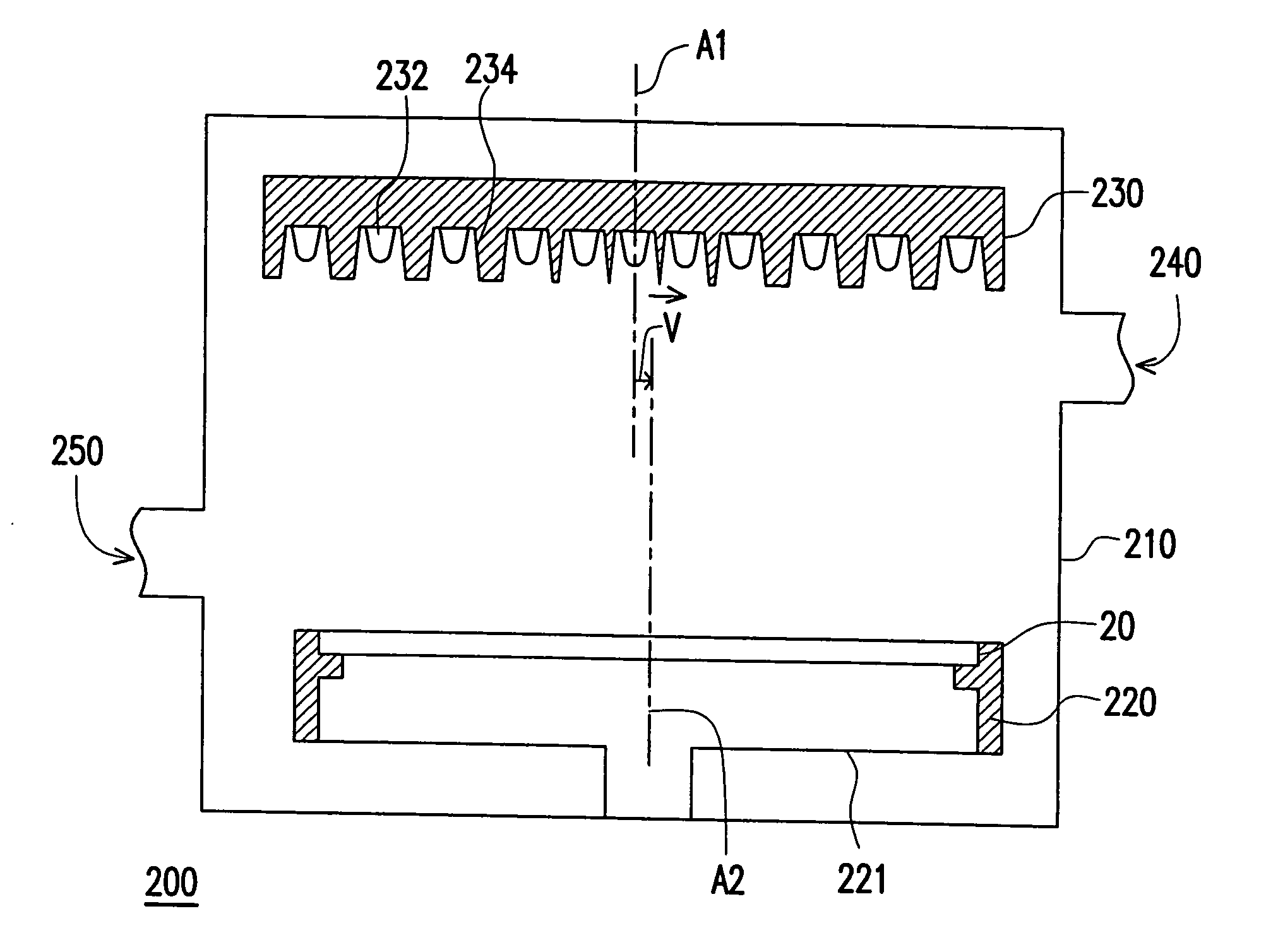
[0036]FIG. 3A is a schematic cross-sectional view of a thermal processing apparatus in the first embodiment of the present invention. FIG. 3B is a drawing, schematically showing a partial plan view of the set of heating lamps in FIG. 3A. Referring to FIGS. 3A and 3B, a thermal processing apparatus 200 of the present invention comprises, for example, a chamber 210, a rotatable supporter 220, a set of heating lamps 230, a gas intake 240 and an exhaust outlet 250. Wherein, the rotatable supporter 220, such as a wafer supporter, and the set of heating lamps 230 are disposed inside the chamber 210, and the set of heating lamps 230 is located over the rotatable supporter 220. The centerline A2 of object 20 is parallel to the array centerline A1 of the set of heating lamps 230. The set of heating lamps 230 comprises a plurality of heating lamps 232 and reflectors 234, and the heating lamps 232 are, for example, infrared halogen lamps. A heated object 20 is placed on the...

second embodiment

The Second Embodiment

[0041]FIG. 4 is a cross-sectional view, schematically illustrating a thermal processing apparatus according to a second embodiment of the present invention. Unlike the above-described thermal processing apparatus 200 in the first embodiment, the set of heating lamps of the thermal processing apparatus 300 in the second embodiment is rotatable, and the supporter 320 of the thermal processing apparatus 300 is not rotated. Remarkably, the offset V is also arranged. The set of heating lamps 330 rotates eccentrically around the centerline B2 of the heated object. This is equivalent to that the heated object 20 rotates about the centerline B2 thereof and with an offset as shown in the first Embodiment. As to the other components and the relative positions thereof of the thermal processing apparatus 300 are the same as those in the first embodiment, so descriptions for the other components are omitted for simplicity. In the same way as the first embodiment of the prese...

third embodiment

The Third Embodiment

[0042]FIG. 5 is a schematic section view of a thermal processing apparatus in the third embodiment of the present invention. Unlike the above-described thermal processing apparatus 200 in the first embodiment, the set of heating lamps of the thermal processing apparatus 400 in the third embodiment is also rotatable. In other words, both the set of heating lamps 430 and the heated objected 20 are all in rotation. One possibility is that the heated object 20 rotates about the centerline B2 thereof and the set of heating lamps 430 rotates eccentrically about the centerline B2 of heated object 20 as well. As a result, a relative eccentric rotation of the set of heating lamps 430 with respect to the heated objected 20 is achieved. As to the other components and the relative positions thereof of the thermal processing apparatus 400 are the same as those in the first embodiment, so the descriptions of the other components are omitted for simplicity. In the same way as t...


PUM


Abstract

An adjusting technology of thermal processing is provided. A heating lamp and a reflector are disposed over a wafer and the heat flux distribution on the wafer generated by the individual heating lamp is measured and adjusted. A set of heating lamps formed by heating lamps is disposed over the wafer. The heating lamps are in concentric rings and arranged as an axi-symmetric array. The relative position between the set of heating lamps and the wafer is adjusted so that the wafer center is at the position with local mean heat flux from lamps between the most inner lamp subset and its adjacent lamp subset. Followed by adjusting the heating powers, either or both of the wafer and the set of heating lamps are rotated respect to the center of the wafer, so as to improve uniformity of the heat flux distribution on the heated object.

Description

CROSS-REFERENCE TO RELATED APPLICATION [0001] This application is a continuation-in-part of a prior application Ser. No. 11 / 135,850, filed May 23, 2005. All disclosures are incorporated herewith by reference.BACKGROUND OF THE INVENTION [0002] 1. Field of Invention [0003] The present invention relates to an apparatus and an adjusting technology for a uniform thermal processing and particularly for uniformly heating wafers. [0004] 2. Description of the Related Art [0005] Along with the advances of science and technology and the steady enhancement of living quality plus the continuously growing of computers and the peripheral industries thereof, the IC (integrated circuit) application fields are wider and wider. As to the IC devices in current applications, the silicon wafers are used as the base material for the most IC substrates. On a wafer, a number of semiconductor processes, such as layer deposition, lithographing, etching, removing the photoresist, and followed by packaging and ...

Claims


Application Information

Patent Timeline
IPC IPC(8): H05B3/60
CPCH05B3/0047H01L21/67115
Inventor SU, CHIUNG-CHIEHYU, MENG-CHIUANTSAO, JEN-CHIEHLIN, MING-JUNESU, YONG-SENLAI, YI-HSIANG
Owner NAT CHUNG SHAN INST SCI & TECH
Why Eureka
Try Eureka