
Heat radiation member and production method for the same

a radiation member and heat radiation technology, applied in the direction of cooling/ventilation/heating modification, semiconductor/solid-state device details, semiconductor devices, etc., can solve the problem of poor conformity of metal sheets, inability to achieve the expected effect of excellent thermal conduction properties of sheets, and inability to direct contact with exothermic parts with satisfactory adhesion, etc. problem, to achieve the effect of effective transmission and diffusion of hea

Inactive Publication Date: 2007-01-04
POLYMATECH CO LTD
View PDF4 Cites 49 Cited by
  • Summary
  • Abstract
  • Description
  • Claims
  • Application Information

AI Technical Summary

Benefits of technology

[0006] The present invention has been made in view of the above-mentioned problems. It is an object of the present invention to provide a heat radiation member for effectively transmitting and diffusing heat from exothermic parts mounted on electronic equipment, and a production method for the same.

Problems solved by technology

However, a thermal diffusion sheet made of graphite or metal cannot be placed in direct contact with exothermic parts with satisfactory adhesion therebetween, because the graphite sheet or metal sheet has poor conformity to the exothermic parts due to high stiffness thereof.
As a result, the expected effect of excellent thermal conduction properties of the sheet may not be obtained.
Meanwhile, in a recent application area of electronic equipment in which the amount of heat generation is increasing, even when the above-mentioned heat radiation member is used, the reduction in contact heat resistance is unsatisfactory.
However, in the thermally conductive material layer made of a phase changing material, handling ease in actual use is unsatisfactory as compared with a conventional solid thermally conductive material layer made of an elastomer-based material.
Further, because the thermally conductive material layer made of a phase changing material softens or melts when it is exposed to high temperature, the thermally conductive layer may shrink and dislocate with respect to exothermic parts.
This may reduce thermal conductivity of the layer.
Therefore, the thermally conductive material made of the phase changing material has poor repairability.
Therefore, the application field for such thermally conductive layers is limited to a narrow range.

Method used


Image

  • Heat radiation member and production method for the same
  • Heat radiation member and production method for the same
  • Heat radiation member and production method for the same

Examples


first embodiment

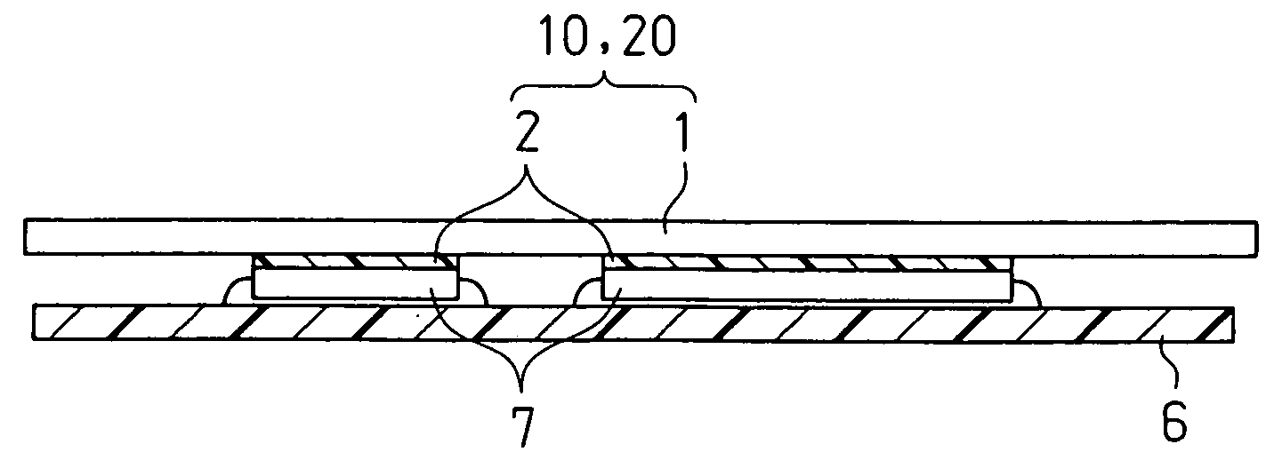
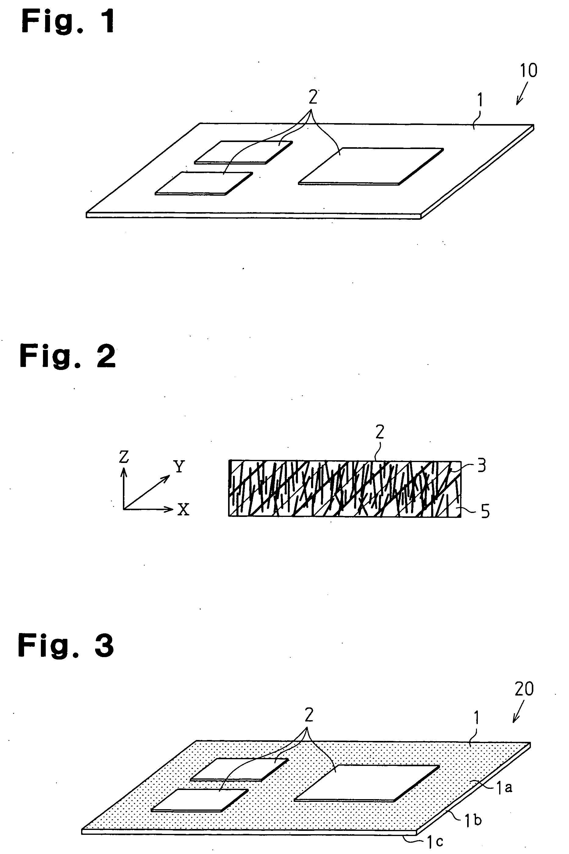
[0019] A heat radiation member according to a first embodiment of the present invention will be described with reference to the accompanying drawings. FIG. 1 shows a perspective view of a heat radiation member 10 according to the first embodiment. The heat radiation member 10 includes a thermal diffusion sheet 1 and thermally conductive polymer layers 2 formed on parts of a top surface of the thermal diffusion sheet 1. Preferably, the thermally conductive polymer layers 2 are selectively formed on the thermal diffusion sheet 1 at positions corresponding to exothermic parts which generate heat when in use. In this embodiment, the thermal diffusion sheet 1 is preferably a graphite sheet.

[0020]FIG. 2 shows a sectional view of the thermally conductive polymer layer 2. The thermally conductive polymer layer 2 contains a polymer material 5 as a matrix and carbon fibers 3 as a thermally conductive filler. In the thermally conductive polymer layer 2, the carbon fibers 3 are oriented in suc...

second embodiment

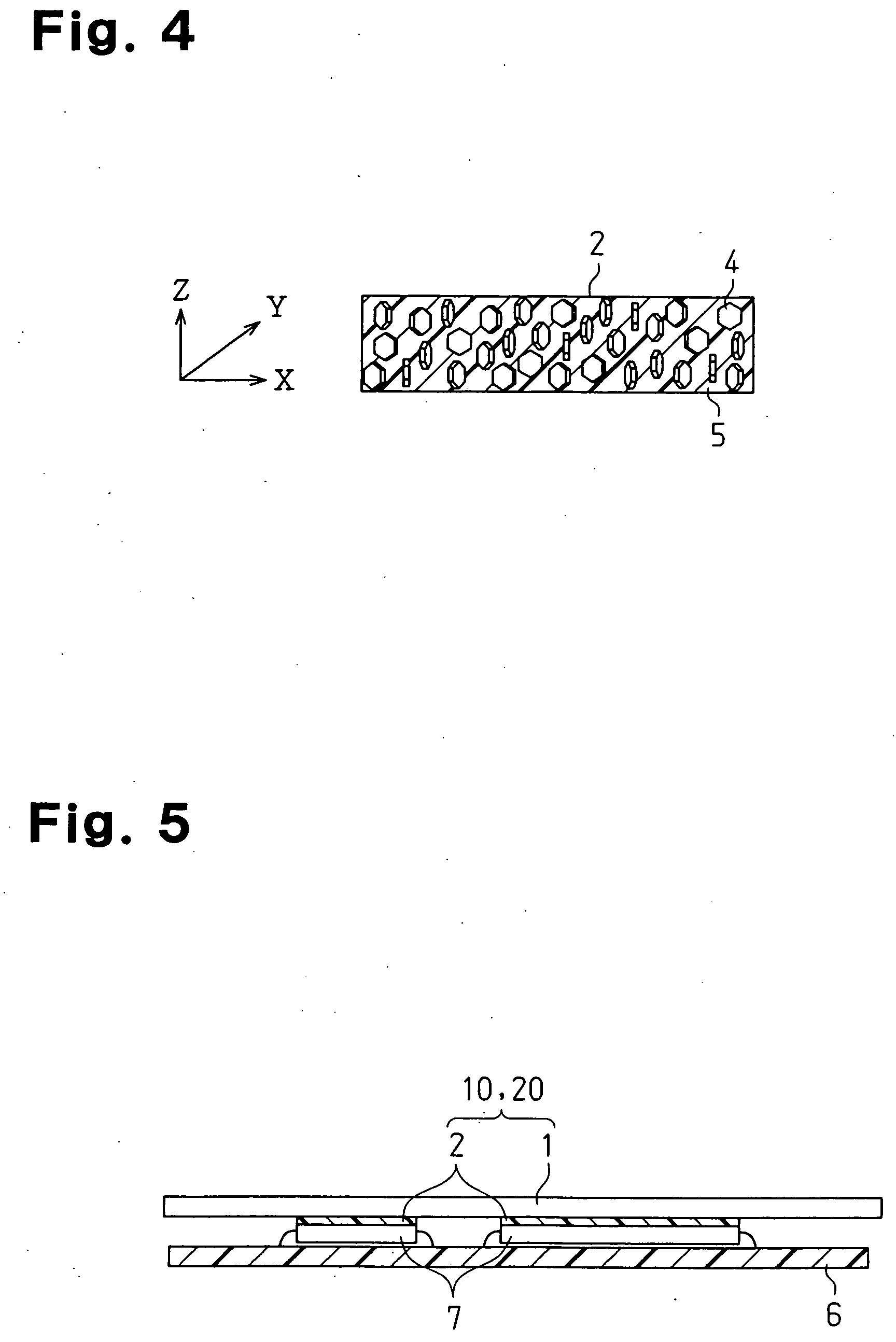
[0025] A heat radiation member according to a second embodiment of the present invention will be described with reference to FIGS. 3 to 5. The heat radiation member 20 shown in FIG. 3 includes the thermal diffusion sheet 1 and the thermally conductive polymer layers 2 formed on the thermal diffusion sheet 1. Preferably, the thermally conductive polymer layers 2 are selectively formed on the thermal diffusion sheet 1 at least at positions corresponding to exothermic parts that generate heat when in use. In this embodiment, the thermal diffusion sheet 1 is preferably a composite sheet consisting of a graphite sheet 1b and aluminum foils 1a and 1c formed on the entire both sides of the graphite sheet 1b. FIG. 4 shows a sectional view of the thermally conductive polymer layer 2. In this embodiment, the thermally conductive polymer layer 2 includes the polymer material 5 as a matrix and hexagonal boron nitride powders 4, which is in the form of scales, as a thermally conductive filler. I...

example 1

[0058] Firstly, 70 parts by weight of graphitized carbon fibers (produced by Nippon Graphite Fiber Corporation, average fiber diameter: 9 μm, average fiber length: 100 μm) and 150 parts by weight of aluminum oxide powders (produced by Showa Denko K.K., in spherical shape, average particle size: 3.5 μm) as thermally conductive fillers were mixed with 100 parts by weight of liquid silicone rubber (produced by GE Toshiba Silicone Co., Ltd.) as a polymer material 5. The resultant mixture was vacuum defoamed to prepare a thermally conductive polymer composition. Subsequently, this thermally conductive polymer composition was injected into a cavity of a mold having a shape corresponding to a predetermined sheet. A magnetic field (magnetic flux density of 10 tesla) was applied in such a manner that the lines of magnetic force corresponded to the thickness direction of the thermally conductive polymer composition in the cavity. Thereby, the graphitized carbon fibers in the thermally conduct...


PUM


Abstract

A heat radiation member including a thermal diffusion sheet; and a thermally conductive polymer layer provided on at least a part of the thermal diffusion sheet. Thermal conductivity of the thermally conductive polymer layer in a thickness direction of the layer is higher than thermal conductivity of the thermally conductive polymer layer in a direction parallel to the surface of the layer. The heat radiation member is formed by joining an independently formed thermally conductive layer including a thermally conductive filler onto the thermal diffusion sheet. The thermally conductive filler are oriented in a specific direction. Alternatively, the heat radiation member is formed by placing a thermally conductive polymer composition containing a thermal conductive filler containing a thermally conductive filler onto the thermal diffusion sheet, orienting the thermally conductive filler in a specific direction, and curing the thermally conductive polymer composition while the orientation is maintained.

Description

BACKGROUND OF THE INVENTION [0001] The present invention relates to a heat radiation member for radiating heat generated from semiconductor devices and electronic parts, and to a production method for the same. [0002] Up to now, in electronic equipment, heat generated from exothermic parts such as semiconductor devices and electronic parts mounted on a circuit board is transmitted to a cooling member such as a heat sink or a cooling fan to be radiated. To this end, a flexible thermally conductive sheet containing a thermally conductive filler, thermally conductive grease, a thermally conductive adhesive, or a thermally conductive phase changing material has been used at an interface between those exothermic parts and the cooling member. Along with achieving sophisticated functions, higher performance, downsizing, and thinning in final products, space for installing a substrate including exothermic parts thereon is becoming narrower in the equipment. Therefore, in recent years, use o...

Claims


Application Information

Patent Timeline
IPC IPC(8): H01L23/34
CPCH01L23/3733H01L23/3735H01L23/3737H01L2924/12044H01L2924/0002H01L2224/32245H01L2224/32225H01L24/29H01L2224/2929H01L2224/29386H01L2224/29393H01L2224/29499H01L2924/00H01L2924/12042H05K7/20
Inventor OHTA, MITSURUYAMAZAKI, JUNTOBITA, MASAYUKI
Owner POLYMATECH CO LTD
Features
  • Generate Ideas
  • Intellectual Property
  • Life Sciences
  • Materials
  • Tech Scout
  • Unparalleled Data Quality
  • Higher Quality Content
  • 60% Fewer Hallucinations
Learn More