Molding composition and method, and molded article
a technology of composition and molding, applied in the field of molding composition and method, and molded articles, can solve the problems of reduced flow, impaired moldability, and high filler levels
- Summary
- Abstract
- Description
- Claims
- Application Information
AI Technical Summary
Problems solved by technology
Method used
Image
Examples
examples 1-4
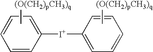
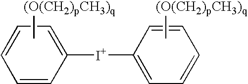
[0132] The compositions detailed in Table 1 were mixed as described above. Examples 1-3 are comparative examples. All component amounts in Table 1 are expressed in parts by weight. Example 4 is an example of the present invention. “Denka FB570 silica” is a fused silica obtained from Denka having a median particle size of 17.7 micrometers and a surface area of 3.1 meter2 / gram. “Denka SFP silica” is a fused silica obtained from Denka having a median particle size of 0.7 micrometers and a surface area of 6.2 meter2 / gram. “Yuka RSS1407LC epoxy”, obtained from Yuka Shell, is 3,3′,5,5′-tetramethyl-4,4′-diglycidyloxybiphenyl. “Sumitomo ECN-195XL-25”, obtained from Sumitomo Chemical, is an epoxidized ortho-cresol novolac resin. “OPPI” is 4-octyloxyphenyl phenyl iodonium hexafluoroantimonate available from GE Advanced Materials-Silicones as UV9392c. “OPPI O3SC4F9” is 4-octyloxyphenyl phenyl iodonium nonafluoro-n-butane sulfonate. It was prepared as follows: 50 grams of 4-octyloxyphenyl pheny...
examples 5 and 6
[0134] The materials listed in Table 3 were mixed as described above to produce curable compositions. Example 5 is a comparative example while Example 6 is an example of the use of the present invention.
TABLE 3IngredientExample 5Example 6Denka FB570 Silica15751429.02Denka SFP Silica175158.78Nippon Kayaku NC-3000 Epoxy Resin235.3212.44OPPI2.352.12OPPI O3SC4F901.06Benzopinacole2.352.12Carnauba Wax6.05.44Carbon Black4.03.63
[0135] Measured property values are presented in Table 4, below. These data once again demonstrate that increased spiral flows can be achieved with the mixed catalysts.
TABLE 4TestExample 5Example 6Spiral Flow (cm) at 175° C.70.691.4Spiral Flow (cm) at 165° C.94.7112.5CTE1 (ppm / ° C.)108.7CTE2 (ppm / ° C.)3934Tg (° C.)141148Moisture Abs. (%)0.1660.209Flex Strength (MPa)130.8127.7
Examples 7 and 8
[0136] The materials listed in Table 5 were mixed as described above to give curable compositions. Example 7 is a comparative example at 90% filler loading while Example 8 is...
examples 7 and 8
[0138] Molding compounds containing 4-octyloxyphenyl phenyl iodonium hexafluoroantimonate (“OPPI SbF6−”) and either 4-octyloxyphenyl phenyl iodonium triflate (“OPPI CF3SO3−”) or 4-octyloxyphenyl phenyl iodonium hexafluorophosphate (“OPPI PF6−”) were prepared and tested as described above. Samples of 4-octyloxyphenyl phenyl iodonium triflate and 4-octyloxyphenyl phenyl iodonium hexafluorophosphate were obtained from Hampford Research.
TABLE 7IngredientExample 7Example 8Denka FB570 Silica15301530Denka SFP Silica170170Yuka RSS1407LC Epoxy56.5956.59Sumitomo ECN-195XL-25226.34226.34OPPI SbF6−2.832.83OPPI CF3SO3−1.410OPPI PF6−01.41Benzopinacole2.832.83Carnauba Wax6.006.00Carbon Black4.004.00
[0139] Measured property values are presented in Table 8, below. Compared to Example 3 above, Examples 7 and 8 exhibited significantly enhanced spiral flow.
TABLE 8PropertyExample 7Example 8Spiral Flow (in) at 175° C.49.449.0Spiral Flow (in) at 165° C.Not Tested58.0Moisture Abs. (%)0.1870.226Flex Str...
PUM
| Property | Measurement | Unit |
|---|---|---|
| softening point | aaaaa | aaaaa |
| particle size | aaaaa | aaaaa |
| particle size | aaaaa | aaaaa |
Abstract
Description
Claims
Application Information
 - R&D
- Intellectual Property
- Life Sciences
- Materials
- Tech Scout
- Unparalleled Data Quality
- Higher Quality Content
- 60% Fewer Hallucinations
Browse by: Latest US Patents, China's latest patents, Technical Efficacy Thesaurus, Application Domain, Technology Topic, Popular Technical Reports.
© 2025 PatSnap. All rights reserved.Legal|Privacy policy|Modern Slavery Act Transparency Statement|Sitemap|About US| Contact US: help@patsnap.com


