
Ultrasonic array probe apparatus, system, and method for traveling over holes and off edges of a structure

a technology of ultrasonic array and probe apparatus, which is applied in the direction of instruments, heat measurement, specific gravity measurement, etc., can solve the problems of not always being able to perform continuous scanning of the structure with holes, introducing additional time and labor, and restricting the access to the interior surface of the structur

Active Publication Date: 2007-01-11
THE BOEING CO
View PDF8 Cites 46 Cited by
  • Summary
  • Abstract
  • Description
  • Claims
  • Application Information

AI Technical Summary

Benefits of technology

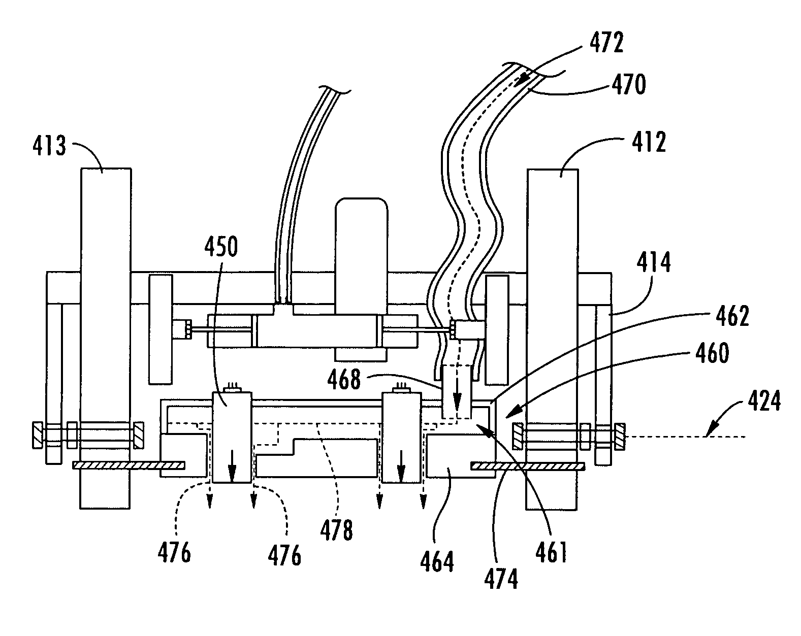
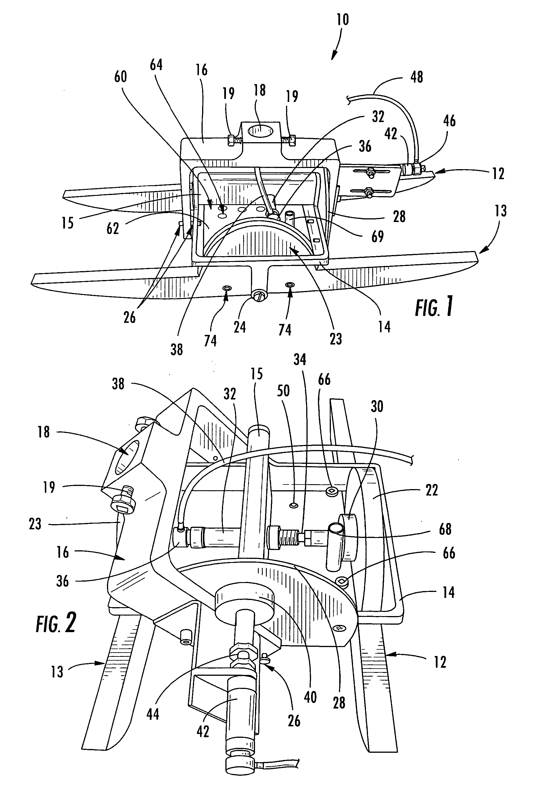
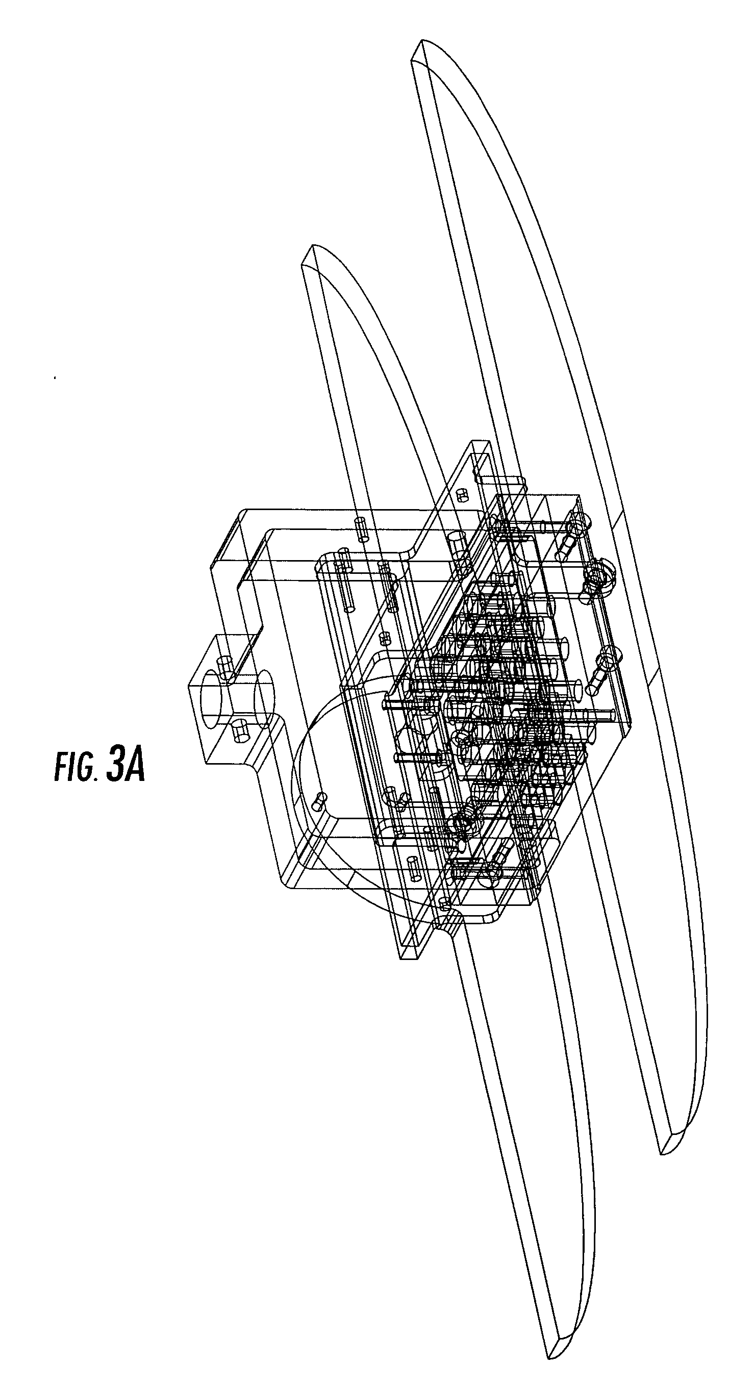
[0010] The present invention provides an improved apparatus, systems, and methods for inspecting a structure using an inspection probe that includes sled-like appendages, referred to herein as sled appendages or sleds, an axial braking system and a probe extension braking system. Inspection probes according to the present invention may be used in conjunction with a motion control system that both moves the probe over the structure for inspection and operates with the axial and extension braking systems for when the probe travels over holes or off edges of the structure. An inspection probe may also be used with an extension coupling device between the motion control system and the probe to press the probe against the structure for adjusting to changes in surface contours of the structure, rather than requiring the motion control system to make detailed changes in orientation and movement of the probe to adjust to changes in surface contours. Either the motion control system or a separate device, such as an extension coupling device, would be used to press the inspection probe against the structure so the inspection probe will ride across the structure on the sled appendages. Embodiments of the present invention combine the physical structure of the sled appendages with the axial braking system to fix the position of the sled appendages for traveling over holes or off an edge of the structure, including large holes or cut-outs in the structure which are also referred to herein as holes. Embodiments of the present invention can be used for various inspection applications but are particularly useful for inspection of structures that include holes and require inspection of the edges around the structure or defining a hole or have contoured surfaces. A probe will include one or more sensors, typically pulse echo ultrasonic transducers, possibly defining an array of pulse echo ultrasonic transducers. Such devices can be used for high resolution defect detection in structures of varying shapes and sizes. Embodiments of apparatus, systems, and methods of the present invention can be used for inspection of structures during manufacture or in-service. Further, embodiments of the present invention provide new inspection capabilities for non-destructive inspection of large and small structures, particularly including the edges of structures and structures with holes.
[0011] Embodiments of apparatus, systems, and methods of the present invention typically operate in array modes using an array of pulse echo ultrasonic transducers, thereby increasing inspection speed and efficiency while reducing cost. Apparatus, systems, and methods of the present invention are also capable of operating with a single or a plurality of pulse echo ultrasonic transducers.
[0012] For continuous scanning applications, embodiments of apparatus, systems, and methods of the present invention permit the probe to contact and ride along the surface of the structure using one or more sled appendages, thereby reducing the necessary sophistication of a motion control system that is typically required by conventional scanning systems to maintain the probe in a predefined orientation and predefined position with respect to the surface of the structure. By allowing the probe to ride across the structure, the motion control system, or a separate device such as an extension coupler, only needs to press the probe against the structure, but does not need to know the surface contours of the structure because the act of pressing the probe against the surface combined with the sled appendages having freedom of motion and the axial motion of the probe compensate for surface contours. In addition to sled appendages, the probe may also use contact members to support the probes against the respective surfaces of the structure, such as roller bearings along the bottom of the sled appendages. The sled appendages are rotatably connected to permit freedom of motion of the sled appendages for riding along contoured surfaces. Contact with the surface ensures consistent orientation of transducers with respect to the structure for pulse echo ultrasonic inspection. Contact with the surface also permits accurate position measurement of the inspection device during continuous scanning, such as keeping an optical or positional encoder in physical and / or visual contact with the surface of the structure under inspection. Contact with the surface also permits the probe to disperse a couplant between the surface of the structure and the pulse echo ultrasonic transducers. Where a couplant is used, a probe may also include a bubbler shoe that disperses the couplant around each pulse echo ultrasonic transducer to independently couple the signal from each transducer to the surface of the part. By individually coupling each transducer to the surface of the part, the bubbler shoe compensates for when the probe travels over a hole or off an edge of the structure where all of the transducers are not over the surface of the structure. In such a manner, only the probes over the hole or off the edge of the structure will lose the coupling with the surface, but the transducers remaining over the surface of the structure will continue to be independently coupled.
[0014] According to one aspect of the present invention, an apparatus, system, and method for non-destructive inspection of a structure includes a probe which is configured for traveling over a surface of the structure along sled appendages and using an axial braking system for traveling over holes and off edges of the structure. The probe includes at least one pulse echo ultrasonic transducer. A plurality of pulse echo ultrasonic transducers may be arranged in an array for faster and more complete scanning of the structure. If a couplant is used to couple the transducers to the surface of the structure, the probe may include a bubbler shoe to individually couple each transducer to the surface of the structure to prevent loss of coupling of transducers remaining over the surface of the structure when one or more transducers are over a hole or off an edge. The probe may also include a visual inspection sensor for providing position or optical information related to the location of the probe or transducers thereof.

Problems solved by technology

In the field, access to interior surfaces of the structure is often restricted, requiring disassembly of the structure, introducing additional time and labor.
For example, typical defects in composite sandwich structures, generally made of one or more layers of lightweight honeycomb or foam core material with composite or metal skins bonded to each side of the core, include disbonds which occur at the interfaces between the core and the skin or between the core and a buried septum.
However, it has traditionally not always been possible to perform continuous scanning of a structure with holes and off the edges of the structure.
However, for through-transmission ultrasonic inspection, a semi-automated inspection system requires access to both sides or surfaces of a structure which, at least in some circumstances, will be problematic, if not impossible, particularly for semi-automated systems that use a fixed frame for control of automated scan heads.
Conventional automated scanning systems, such as the AUSS-X system, therefore require access to both sides or surfaces of a structure for through transmission inspection which, at least in some circumstances, will be problematic, if not impossible, particularly for very large or small structures.
Further, most structures require inspection of edges around the structure and defining holes in the structure.

Method used


Image

  • Ultrasonic array probe apparatus, system, and method for traveling over holes and off edges of a structure
  • Ultrasonic array probe apparatus, system, and method for traveling over holes and off edges of a structure
  • Ultrasonic array probe apparatus, system, and method for traveling over holes and off edges of a structure

Examples


Embodiment Construction

[0023] The present invention will be described more fully with reference to the accompanying drawings. Some, but not all, embodiments of the invention are shown. The invention may be embodied in many different forms and should not be construed as limited to the described embodiments. Like numbers and variables refer to like elements and parameters throughout the drawings.

[0024] The term “holes” refers to holes of varying sizes in a structure, including features described as “cut-outs” in the structure. The term “edges” refers generally to the sides of the structure, but also includes reference to the perimeter of holes, particularly large holes or cut-outs through which a conventional part-riding probe might fall through. Thus, holes may be described as having edges, and the term edges is inclusive of both an external perimeter of a structure and perimeters of internal holes in the structure. Although being characteristically different, for purposes of the present invention holes a...


PUM

PropertyMeasurementUnit
structureaaaaaaaaaa
pressureaaaaaaaaaa
porosityaaaaaaaaaa

Abstract

Improved apparatus, systems, and methods for inspecting a structure are provided that use a probe with sled appendages and an axial braking system. The probe uses pulse echo ultrasonic signals to inspect the structure. The sled appendages permit the probe to contact and ride along the surface of the structure and are rotatably connected and curved away from the surface of the structure to compensate for contoured surfaces and inspection around holes and edges. The axial braking system, in coordination with a motion control system moving the probe, fixes the positions of the sled appendages just before the probe travels over a hole or off an edge of the structure to prevent the probe from falling through the hole or off an edge and to permit the probe to return to the surface of the structure to continue inspection of the structure.

Description

CROSS-REFERENCE TO RELATED APPLICATIONS [0001] The contents of U.S. Pat. No. 6,722,202; application Ser. No. 10 / 752,890, entitled “Non-Destructive Inspection Device for Inspection Limited-Access Features of a Structure,” filed Jan. 7, 2004; application Ser. No. 10 / 943,088, entitled “Magnetically Attracted Inspecting Apparatus and Method Using a Ball Bearing,” filed Sep. 16, 2004; application Ser. No. 10 / 943,135, entitled “Magnetically Attracted Inspecting Apparatus and Method Using a Fluid Bearing,” filed Sep. 16, 2004; and application Ser. No. 11 / ______, entitled “Ultrasonic Inspection Apparatus, System, and Method,” filed Jul. 11, 2005, are incorporated by reference.FIELD OF THE INVENTION [0002] The present invention relates generally to an apparatus, system, and method for inspecting a structure and, more particularly, to an apparatus, system, and method for non-destructive pulse echo ultrasonic inspection of a structure and inspection near holes and edges of the structure. BACKG...

Claims


Application Information

Patent Timeline
Patent Type & Authority Applications(United States)
IPC IPC(8): G01N29/00
CPCG01N29/225G01N2291/2694G01N2291/044G01N29/265
Inventor KENNEDY, JAMES C.LITTLE, MARK L.UYEHARA, CLYDE T.
Owner THE BOEING CO
Learn More