Rolling/sliding part, rolling bearing, cam follower, and method of modificating surface of rolling/sliding part

Inactive Publication Date: 2007-01-11
JTEKT CORP
View PDF4 Cites 18 Cited by
  • Summary
  • Abstract
  • Description
  • Claims
  • Application Information

AI Technical Summary

Benefits of technology

[0015] A surface modificating method of a rolling/sliding part of the present invention is a surface modificating method of a rolling/sliding part which is used in a state where the rolling/sliding part comes into sliding contact or rolling contact with a mating part. The method includes performing shot-blasting or barrel processing which has an effect on the hardness of only a surface layer portion existing at a depth of, at a maximum, 10 μm from the surface of a base material to be the rolling/sliding part, and repeating the processing until it is confirmed that, when Vickers hardness measurement is performed on the base material after the processing, the hardness A measured under a load of 0.1 N becomes Hv 780 to 900, and the hardness B measured under a load of 1 N becomes lower than the hardness A and less than Hv 780.
[0016] According to the rolling/sliding part of the present invention, it is

Problems solved by technology

Since this hard processing makes the surface of the part rough which becomes a primary factor which causes premature pitching in a contacting mating member, superfinishing for roughness fining is required after the surface modificat

Method used


Image

  • Rolling/sliding part, rolling bearing, cam follower, and method of modificating surface of rolling/sliding part
  • Rolling/sliding part, rolling bearing, cam follower, and method of modificating surface of rolling/sliding part

Examples


Example

Embodiment 1

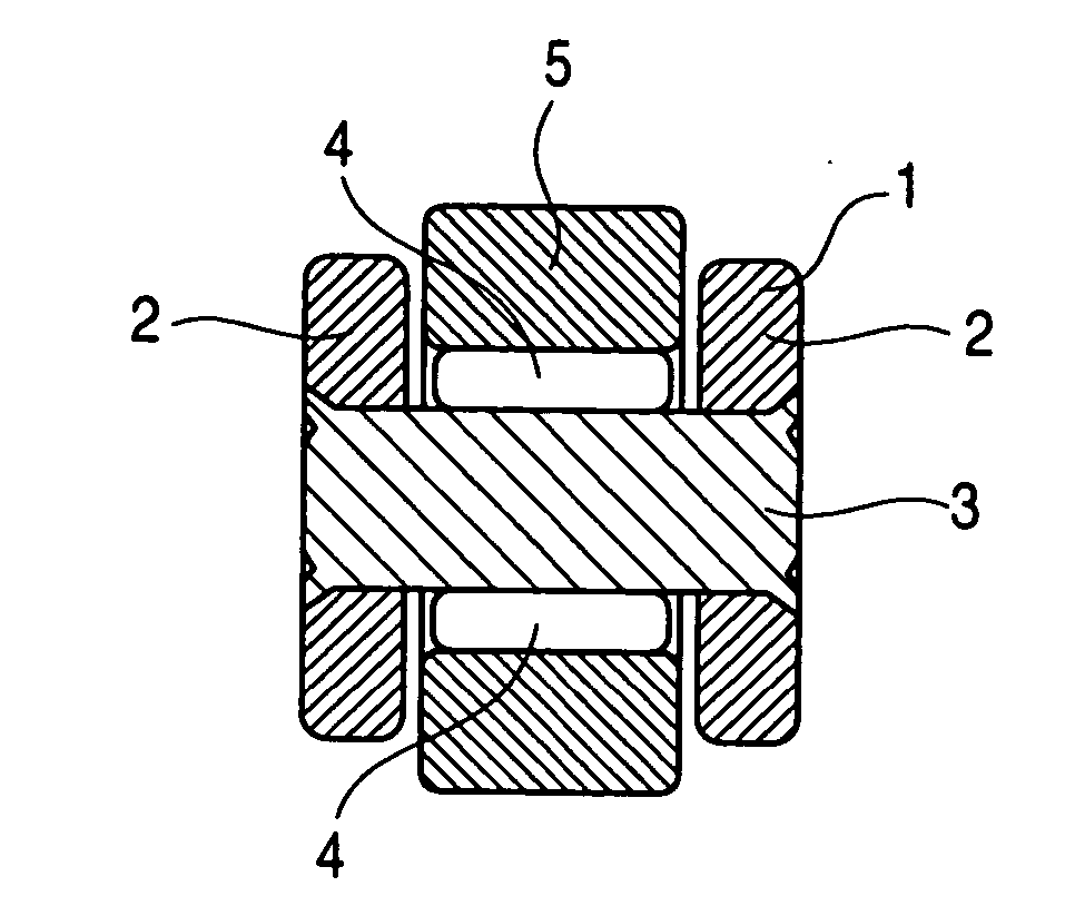
[0022]FIG. 1 is a sectional view of a cam follower according to Embodiment 1 of the present invention. In this cam follower, both ends of a shaft 3 is fixedly supported by a pair of support walls 2 and 2 which are provided with spacing between them at ends of the locker arm 1 which face a cam (not shown), a short cylindrical outer ring 5 is provided around the shaft 3 with rollers 4 and 4 disposed between the outer ring and the shaft, and the outside cylindrical surface of the outer ring 5 and the outside cylindrical surface of the cam is caused to abut on each other so that the outer ring 5 rotates about the shaft 3 with the rotation of the cam. Accordingly, the outer ring 5 corresponds to a rolling / sliding part of the present invention.

[0023] Now, considering that peeling occurring in the outside cylindrical surface of the outer ring 5 is surface peeling which is generated in a surface layer portion up to about 5 μm from a surface layer, the present inventors paid at...

Example

Embodiment 2

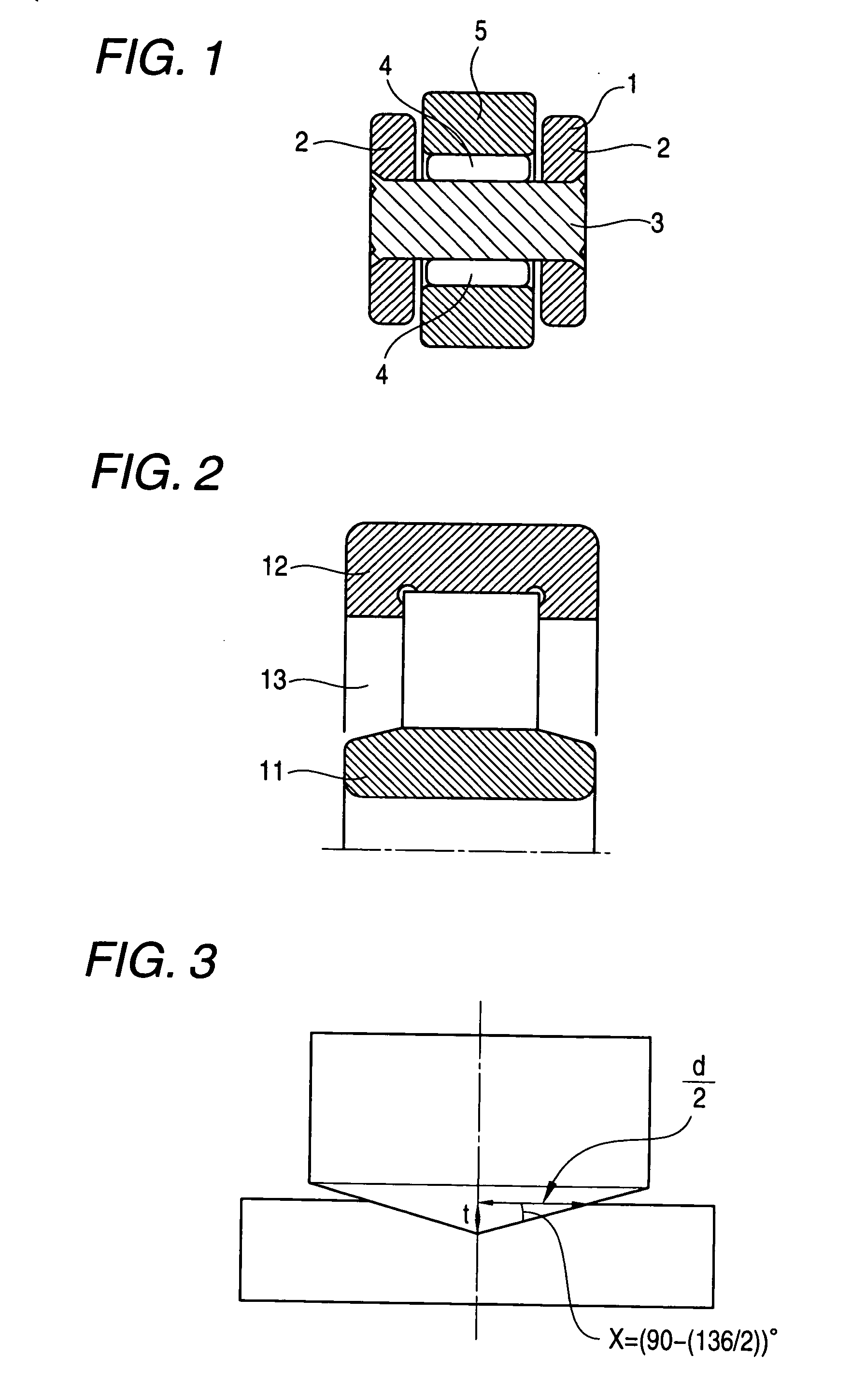
[0038] Although the outer ring 5 of the cam follower is exemplified in Embodiment 1 as a rolling / sliding part with its surface modification, which is used in a state where the rolling / sliding part comes into sliding contact or rolling contact with a mating part, the present invention can also be applied to a rolling bearing. FIG. 2 is a partial sectional view of the roller bearing according to Embodiment 2 of the present invention. This roller bearing is obtained by arranging rolling elements 13 that are a plurality of cylindrical rollers between an inner ring 11 and an outer ring 12 that are bearing rings. In such a cylindrical roller bearing, it is possible to obtain a roller bearing capable of preventing occurrence of peeling and occurrence of pitching to a mating member by subjecting the inner ring 11 and the rolling elements 13 to the surface modificating as described in Embodiment 1.

Example

Embodiment 3

[0039] The outer ring 5, the inner ring 11, and the rolling elements 13, and the like, which have the surface modificating characteristics as described above, are obtained by performing surface modificating on a surface layer portion of a base material to be a rolling / sliding part. Specifically, soft shot-blasting or flow barrel processing which has an effect on the hardness of only a surface layer portion existing at a depth of, at a maximum, 10 μm (preferably about 5 μm) from the surface of the base material is performed on the base material, and this processing is repeated until it is confirmed that, when Vickers hardness measurement is performed on the base material after the processing, the hardness A measured under a load of 0.1 N becomes Hv 780 to 900, and the hardness B measured under a load of 1 N becomes lower than the hardness A and less than Hv 780. Thereby, sliding parts having the surface modificating characteristics of Embodiment 1 can be obtained.

[0040]...


PUM

PropertyMeasurementUnit
Lengthaaaaaaaaaa
Lengthaaaaaaaaaa
Forceaaaaaaaaaa

Abstract

The invention provides a cam follower having an outer ring which is used in a state where the cam follower comes into sliding contact or rolling contact with a mating part. The outer ring is configured such that the hardness of a surface layer portion existing between the surface and at least 3 μm below the surface is Hv 780 to 900, and the hardness of an internal surface portion existing at a depth of 10 μm or more from the surface is lower than the hardness of the surface layer portion and less than Hv 780. Such hardness can be obtained by performing soft shot blasting or flow barrel processing on a surface layer portion of a base material to be the outer ring.

Description

BACKGROUND OF THE INVENTION [0001] The present invention relates to a rolling / sliding part (hereinafter referred to as rolling / sliding part) which is used in a state where the rolling / sliding part comes into sliding contact or rolling contact with a mating part, a rolling bearing, a cam follower, and the like. [0002] In a bearing ring and bearing elements which constitute a bearing or an outer ring which constitutes a cam follower, their surfaces are often peeled (also referred to as “peeling damage.” In order to prevent this peeling, a method of increasing the hardness of surface layer portions of those parts or a method of applying residual compressive stress to the surface layer portions is already known (for example, Patent Documents 1 to 5). [0003] Patent Document 1; Japanese Unexamined Patent Application Publication No. 5-288257 [0004] Patent Document 2: Japanese Unexamined Patent Application Publication No. 5-288221 [0005] Patent Document 3: Japanese Unexamined Patent Applica...

Claims


Application Information

Patent Timeline
IPC IPC(8): C22C38/00
CPCF16C33/34F16C2240/18F16H53/06F16C33/64
Inventor WASEDA, YOSHITAKAOCHI, SHINYA
Owner JTEKT CORP
Why Eureka
Try Eureka