Delay cell for ring oscillator

a delay cell and ring oscillator technology, applied in pulse generators, pulse manipulation, pulse techniques, etc., can solve the problems of unsuitable small-scale cmos integration, and achieve the effects of low power dissipation, small die area, and simple design

Inactive Publication Date: 2007-01-11
CARLETON UNIV
View PDF8 Cites 10 Cited by
  • Summary
  • Abstract
  • Description
  • Claims
  • Application Information

AI Technical Summary

Benefits of technology

[0007] The invention employs a delay cell in a ring oscillator that has a simple design, a small die area, low power dissipation, constant amplitude of oscillation versus control voltage, and a Figure of Merit (FOM) comparable to that of LC oscillators. The invention is particularly well suited for use in multi-band radio systems.

Problems solved by technology

LC oscillators are known to offer excellent phase noise and frequency response, but they are unsuitable for small-scale CMOS integration since they are limited in size by the need for the inductors, which do not scale appropriately with decreasing MOSFET size.
Ring oscillators scale better than LC oscillators, but have not in the past performed as well as LC oscillators.

Method used


Image

  • Delay cell for ring oscillator
  • Delay cell for ring oscillator
  • Delay cell for ring oscillator

Examples


Embodiment Construction

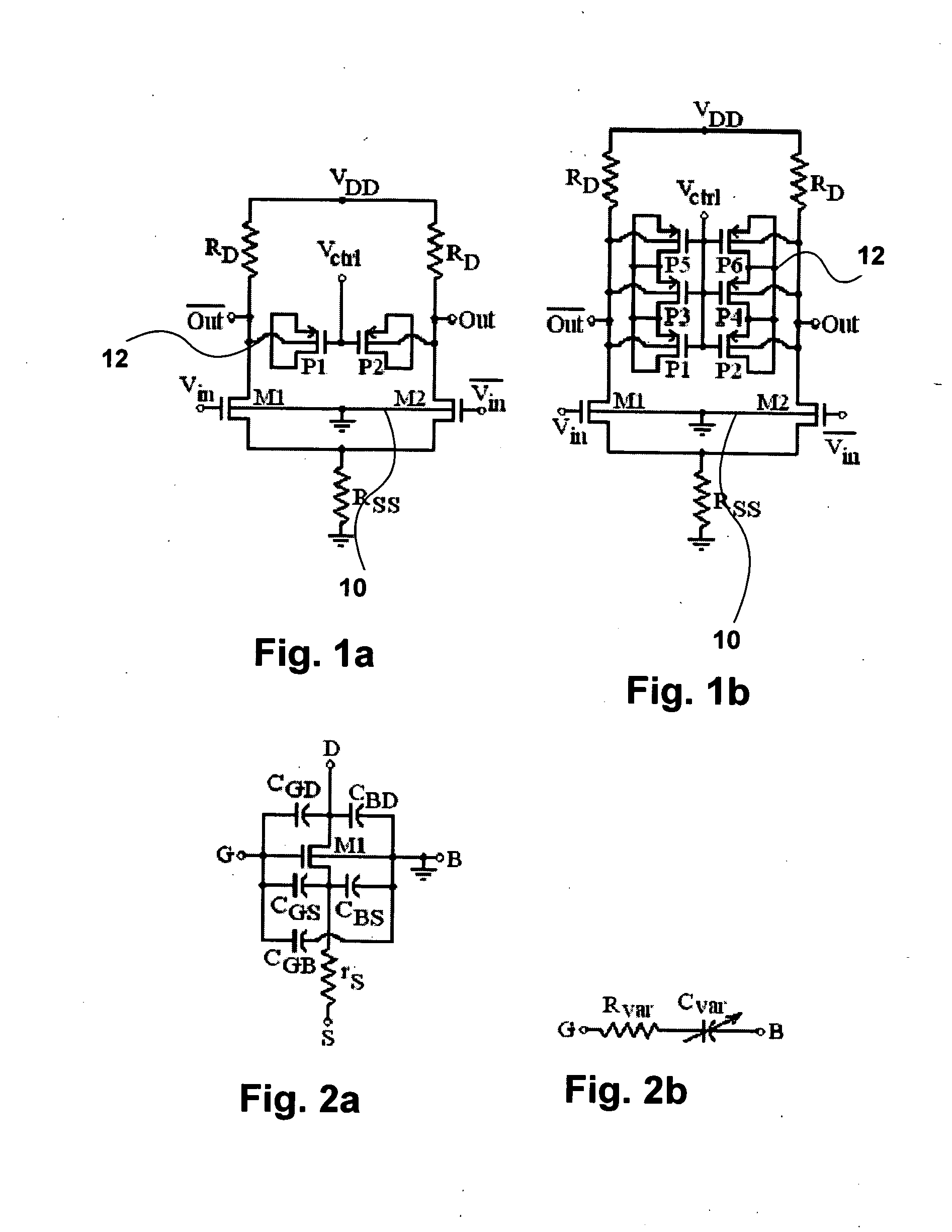
[0019] The novel delay cell in accordance with the principles of the invention employs a resistive element, such as a resistor, as a common source for a differential amplifier. By using a resistive element instead of a common current source, the performance of the oscillator can be considerably improved.

[0020] The delay cell shown in FIG. 1a comprises a differential amplifier 10 consisting of a pair of n-channel MOSFETs M1 and M2 having their substrates connected to ground. The gates of the MOSFETs M1 and M2 are connected to voltage inputs Vin and Vout.

[0021] The sources of the MOSFETs M1 and M2 are connected to ground through a common source resistor RSS. The drains are connected through respective load resistors RD to VDD. FIG. 2a shows an equivalent circuit for the MOSFETs.

[0022] A varactor arrangement of fingers 12 is connected between the drains of the MOSFETs M1 and M2. The varactor arrangement consists of a pair of p-channel MOSFETs P1 and P2 connected at their gates. The ...


PUM


Abstract

A delay cell for use in a voltage controlled oscillator includes a differential amplifier having a pair of outputs, a common source resistive element supplying current to said differential amplifier, a varactor arrangement between the outputs having a control input, and a pair of load resistive elements connected to the respective outputs. The delay cell has a simple design, a small die area, low power dissipation, constant amplitude of oscillation versus control voltage, and a Figure of Merit (FOM) comparable to that of LC oscillators.

Description

CROSS REFERENCE TO RELATED APPLICATION [0001] This application claims the benefit under 35 USC 119(e) for prior U.S. provisional application No. 60\697,533, filed Jul. 11, 2005, the contents of which are herein incorporated by reference.FIELD OF THE INVENTION [0002] This invention relates to the field of voltage-controlled ring oscillators, and in particular to a delay cell for use in such oscillators. BACKGROUND OF THE INVENTION [0003] Timing circuits are required for many applications in digital systems. The basis of most timing circuits is the phase locked loop (PLL), which can be used in frequency synthesis, clock and data recovery, and synchronization. A phase-locked loop is a closed loop feedback system that maintains a generated signal in a fixed phase relationship to a reference signal. A critical element of the PLL is the voltage controlled oscillator, which generates the output signal of the PLL. [0004] The voltage controlled oscillator usually comprising an LC oscillator....

Claims


Application Information

Patent Timeline
IPC IPC(8): H03K3/03
CPCH03K3/0322H03K2005/00208H03K2005/00045H03K5/133
Inventor MILICEVIC, SINISAMACEACHERN, LEONARDMAHMOUD, SAMY
Owner CARLETON UNIV
Why Eureka
Try Eureka