
Manipulation of Projected Images

a projection image and projection technology, applied in image data processing, color television, television systems, etc., can solve the problems of insufficient processing time and processing steps, system only being used, and presenting a less efficient approach to image transformation, so as to reduce the load on the processor and increase the practical refresh rate

Inactive Publication Date: 2007-01-11
MEDINA GERMAN
View PDF3 Cites 35 Cited by
  • Summary
  • Abstract
  • Description
  • Claims
  • Application Information

AI Technical Summary

Benefits of technology

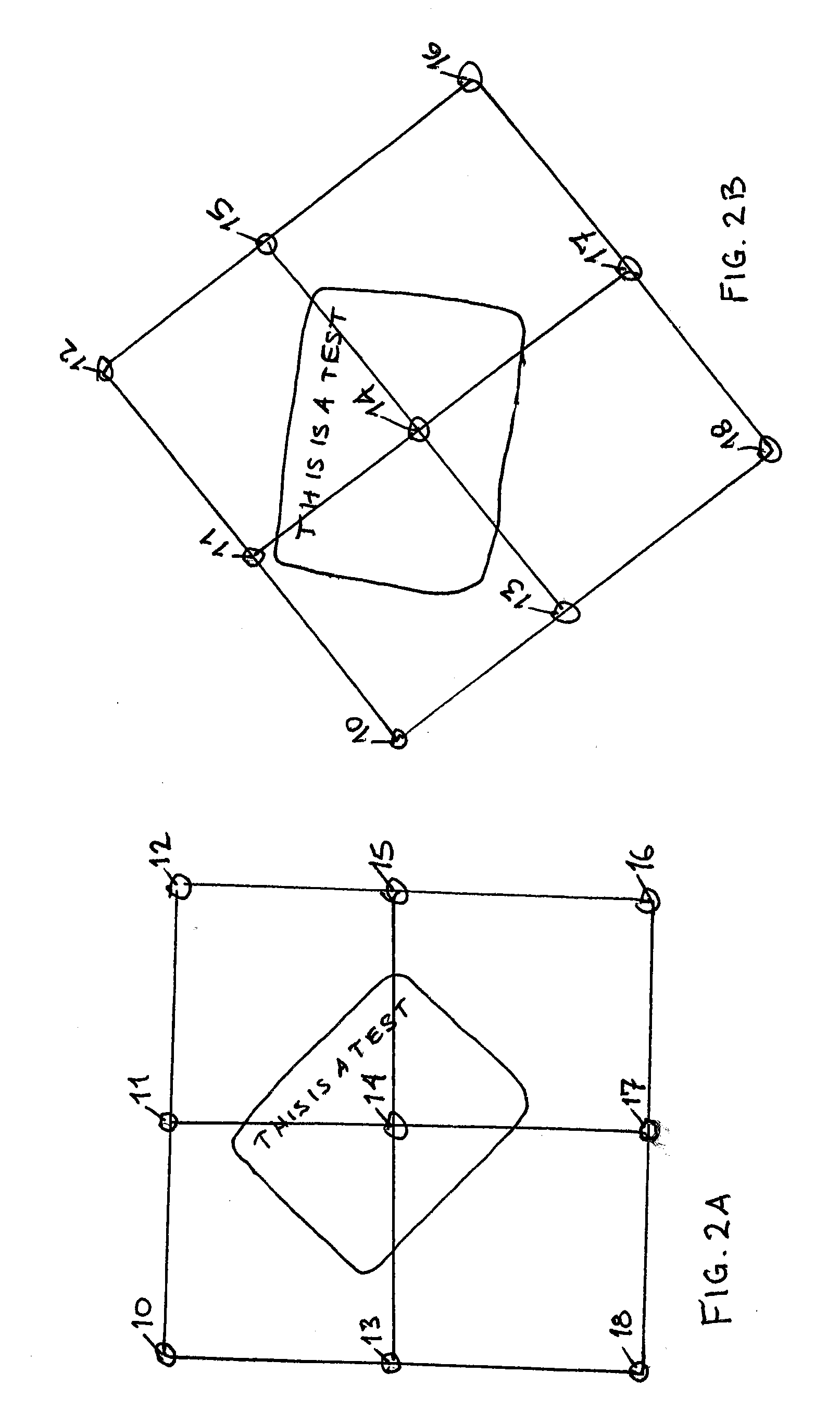
[0007] One advantage of the system is that a user may be capable of selecting and moving one of the plurality of grid points using the user interface, such that moving one of the plurality of grid points automatically defines a transformation algorithm for the transformation processor that it subsequently applied to any image displayed by a projector or monitor. The image may be manipulated by the transformation algorithm and subsequent images may be continuously manipulated by the transformation algorithm, until the user redefines a new transformation algorithm using the user interface. The system is capable of manipulating the images or portions of the images in real time. Another advantage is that video accelerator hardware may be used to increase the refresh rate of any manipulated image using three-dimensional transformations based on a rotational transformation of a plane or the like. A wide variety of mathematical transforms may be applied to manipulated images using known transformation algorithms.
[0009] One advantage is that display of a virtual monitor may be determined by the physics of light in three dimensions using well known 2-D to 3-D transformations. Manipulation of the displayed image, such as to correct for distortions in a projected image, are corrected using three dimensional mathematic transforms which greatly reduces the overhead on the processor compared to manipulations of two dimensional images using pixel by pixel displacement. The technology allows user input to a system that may comprise a personal computer, such as a Pentium® processor having a standard hard drive and system memory for use as a personal computer.2 2Pentium® is a registered trademark of Intel Corporation.
[0010] No special hardware other than the normal resident video card in the computer system needs to be installed in order to transform a video feed in real-time. The video card should have adequate video RAM memory, such as at least 32 megabytes, or more preferably at least 64 megabytes of video RAM, or other similar video image storage memory. The user interface provides the advantage of real-time feedback to the user as the displayed projection is stretched, rotated, resized, positioned, flipped and geometrically corrected from any computer on the network.
[0013] Herein, a computer is defined as any system, device or machine that is capable of accepting instructions from a user, calculating transformations of video images and outputting a video feed to a video display. One advantage is that the system may update the primary desktop's image to the secondary desktop for only the portion of the image that has changed. Another advantage is that the system may copy the information from a memory buffer instead of from the display device. These advantages reduce the load on the processor and are capable of increasing the practical refresh rates for the projected image. Yet another advantage is that three-dimensional algorithms may be applied in real time using the video hardware's acceleration processor that is common in video hardware of common personal computers.
[0014] An user interface is provided that permits the user to see changes in the images as they are applied using an input device such as a pointing device or a remote control, for example. One advantage is that no camera or special frame is required to correct distortions and apply transformations.

Problems solved by technology

However, real-time manipulation of the input field in two dimensions on a pixel by pixel basis requires an inordinate amount of processor time and processing steps.
However, the application requires the use of a camera and a frame on the projection surface in order to derive the mapping for an optimal undistorted image.
This means that the system may only be used with a special screen and camera attached to a computer.
However, such use of a camera or a special frame may present a less efficient approach to transformation of images.
Although macros may be created to apply to a set of still images, it is not possible to continuously apply these complex transforms, which are applied to still images in these programs, to streaming video or at real-time screen refresh rates.
This is a longstanding and unresolved need for which no solution has been forthcoming.

Method used


Image

  • Manipulation of Projected Images
  • Manipulation of Projected Images
  • Manipulation of Projected Images

Examples


Embodiment Construction

[0028] The detailed description and the drawings provide some examples of the invention, but the invention should not be limited merely to the examples disclosed. Instead, the invention should be limited only by the claims that may eventually issue. Many variations in the system, changes in specific components of the system and uses of the system will be readily apparent to those familiar with the field based on the drawings and description provided.

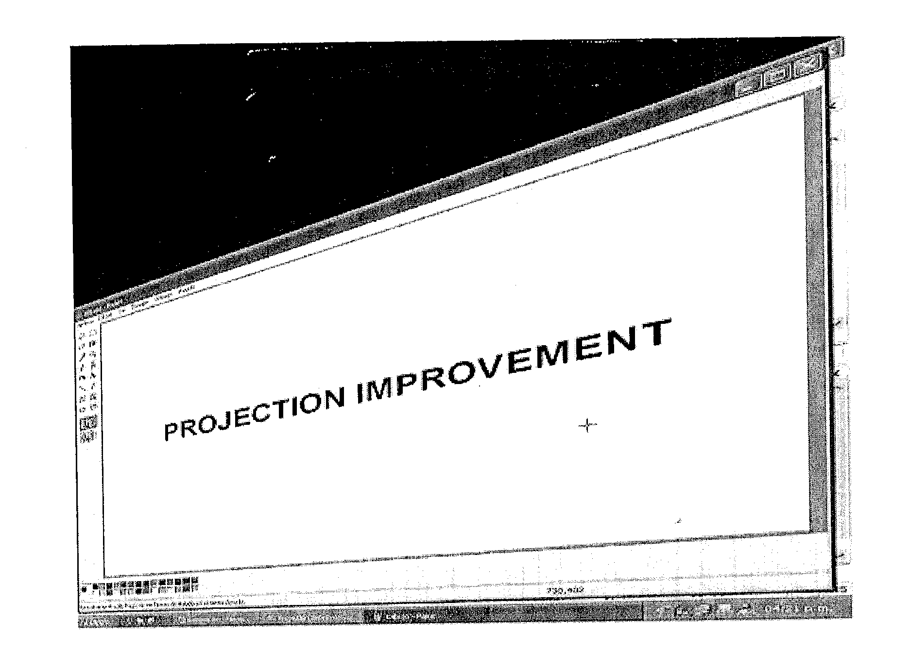
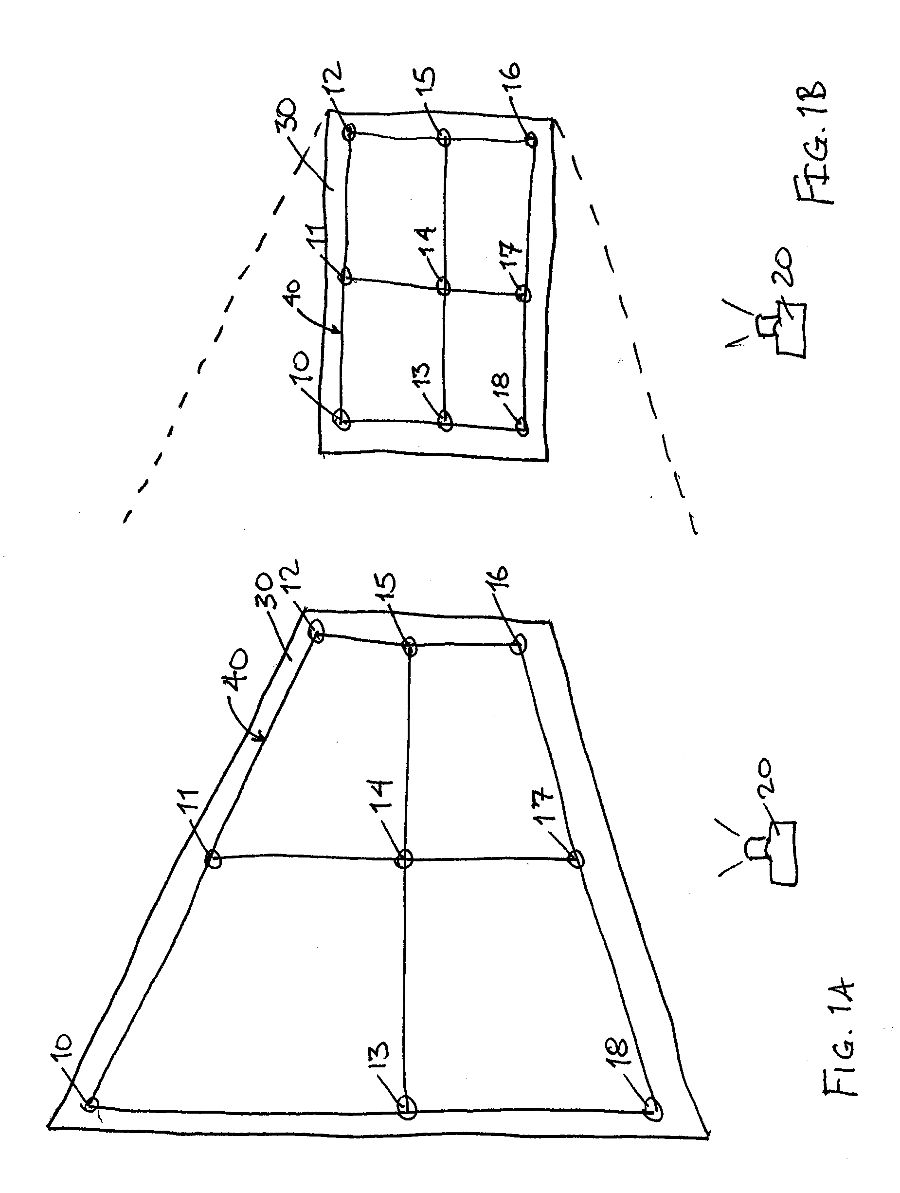
[0029] The image 30 in FIG. 1A is distorted, because the projector 20 is not aligned with the surface on which the image is projected. User input is used to correct the distortion without repositioning the projector. In one embodiment, a remote control may be used to correct the distortion in the image by sending a command to a processor capable of manipulating the image feed. In another embodiment, the distortion is corrected using the pointing device of a computer system, such as a mouse pad, track ball, or other pointing device, to s...


PUM


Abstract

Correction of distorted projections and other visual effects are displayed continuously for still and video images based on three-dimensional transformations that distort or overlay images projected in such a way that the displayed image manipulated. The technology used to remove the distortion is not hardware dependent, may be used with any display device, such as a projector, and is capable of interfacing with the user by remote control, a computer pointing device or any other input device capable of communicating commands to a processor for manipulation of an image.

Description

CROSS-RELATED APPLICATIONS [0001] This application claims the benefit of U.S. Provisional Application No. 60 / 595,162 to German Medina, which was filed on Jun. 10, 2005, the disclosure of which is hereby incorporated by reference herein.FIELD OF THE INVENTION [0002] The field relates to manipulation of projected images under computer control. BACKGROUND [0003] It is known to manipulate images by zooming, positioning and straightening images to eliminate distortions introduced on a display, such as a CRT or projected image. Solutions for manipulating images are ordinarily based on manual manipulation, proprietary hardware or software that corrects distortions on a pixel by pixel basis based on the two dimensional presentation of the image on the display, such as a screen of a CRT or a projector screen. However, real-time manipulation of the input field in two dimensions on a pixel by pixel basis requires an inordinate amount of processor time and processing steps. This relegates real-...

Claims


Application Information

Patent Timeline
IPC IPC(8): G09G5/00
CPCG06T3/00G06T15/10H04N9/3197H04N9/3185H04N5/2628
Inventor MEDINA, GERMAN
Owner MEDINA GERMAN
Learn More