Anode effluent control in fuel cell power plant

a fuel cell and effluent technology, applied in the direction of fuel cells, fuel cell components, fuel cell groupings, etc., can solve the problems the expected improvement of the power generation efficiency cannot be realized, and the hydrogen gas to be used in the power generation reaction is lost, so as to improve the effect of reducing the power generation efficiency of the fuel cell and improving the power generation efficiency

Active Publication Date: 2007-01-11
NISSAN MOTOR CO LTD
View PDF2 Cites 21 Cited by
  • Summary
  • Abstract
  • Description
  • Claims
  • Application Information

AI Technical Summary

Benefits of technology

[0008] It is therefore an object of this invention to enable an improvement in the power generation efficiency of a fuel cell power plant by setting the timing of such an impurity gas removal operation appropriately.

Problems solved by technology

By mixing a small amount of oxygen into the anode gas, not only is carbon monoxide (CO) removed, but a part of the hydrogen reacts with the oxygen to form water (H2O), and hence a part of the hydrogen gas to be used in the power generation reaction is lost.
For such reasons, measures taken in any of the prior art to remove impurity gases may instead lead to a reduction in the power generation efficiency of the fuel cell.
In other words, if the purging timing and oxygen mixing timing in the prior art are not set appropriately, the expected improvement in power generation efficiency cannot be realized.

Method used


Image

  • Anode effluent control in fuel cell power plant
  • Anode effluent control in fuel cell power plant
  • Anode effluent control in fuel cell power plant

Examples


second embodiment

[0071] Next, this invention will be described with reference to FIGS. 8-13.

first embodiment

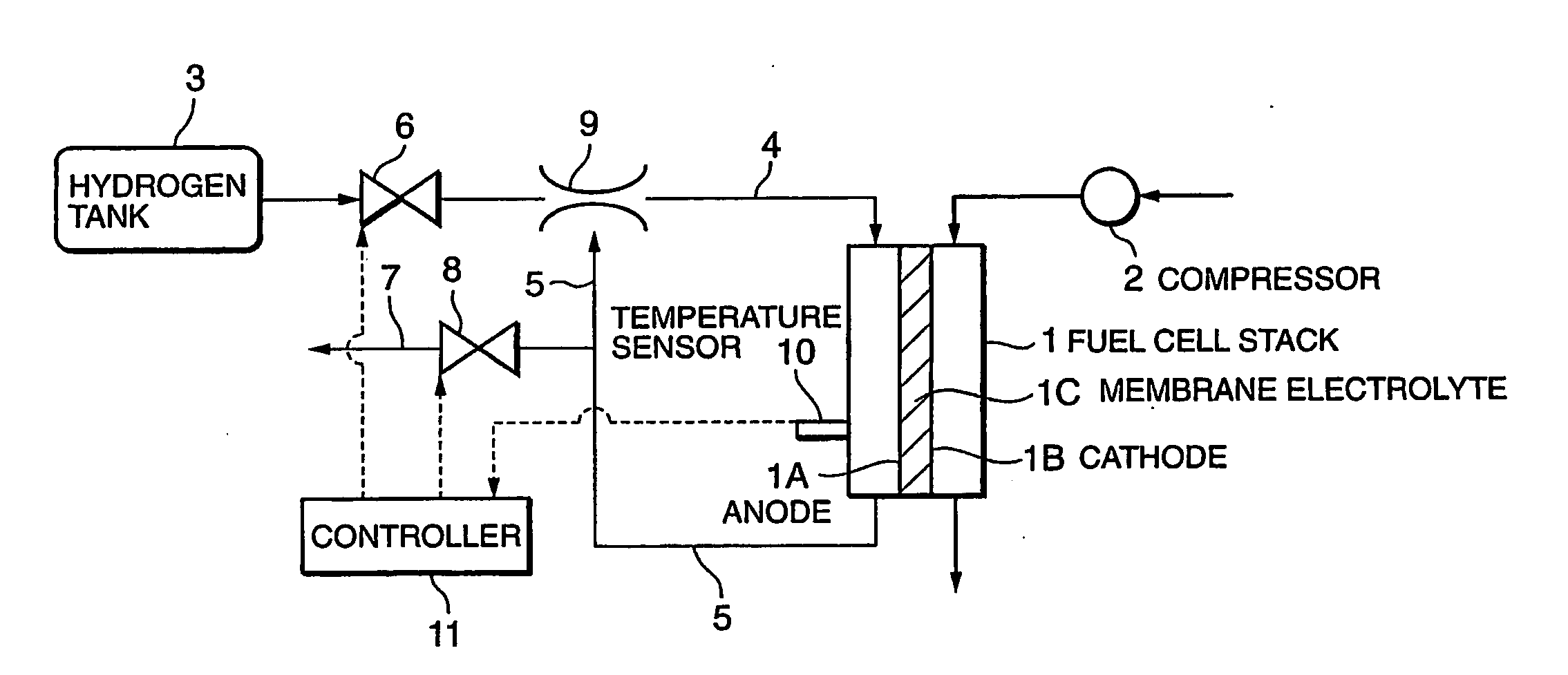
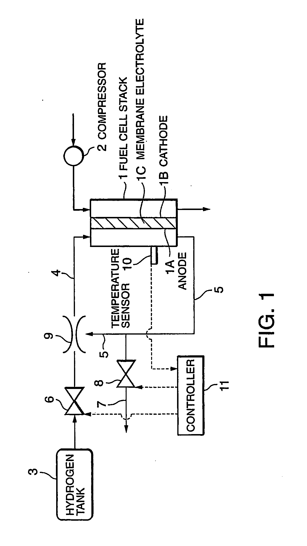
[0072] Referring to FIG. 8, in addition to the constitution of the first embodiment, this embodiment comprises an air supply passage 12, an air supply valve 13, a catalyst 14, and a pump 15. However, the ejector 9 has been omitted from this embodiment.

[0073] The catalyst 14 is provided at a point on the return passage 5. The catalyst 14 functions to remove carbon monoxide (CO) from the anode effluent by means of selective oxidation of the carbon monoxide contained in the anode effluent. The oxidized carbon monoxide thus turns into carbon dioxide (CO2).

[0074] The air supply passage 12 is provided to supply air, which serves as the oxidizing agent used by the catalyst 14, from the compressor 2. The air supply passage 12 is connected to the return passage 5 upstream of the catalyst 14. The air supply valve 13 serves to adjust the air supply flow through the air supply passage 12.

[0075] The pump 15 is provided on the return passage 5 downstream of the catalyst 14, and serves in place ...

third embodiment

[0134] Next, referring to FIG. 14, this invention will be described.

[0135] In this embodiment, a recording device 16 using an integrated circuit (IC) is annexed to the hydrogen tank 3 of the fuel cell power plant according to the second embodiment. The CO concentration of the hydrogen that is stored in the hydrogen tank 3 is recorded on the recording device 16. The CO concentration data are extracted when the hydrogen tank 3 is refilled with hydrogen by means of data communication between the recording device 16 and a refill station which refills the hydrogen tank 3 with hydrogen.

[0136] In cases where the hydrogen for refilling the hydrogen tank 3 contains impurities caused by other inert gases, the recording device 16 preferably records further impurity concentration data.

[0137] The recording device 16 and controller 11 are connected by a signal circuit, and the CO concentration and impurity concentration are provided to the controller 11 as signals. Similarly to the second embod...


PUM

PropertyMeasurementUnit
energy lossaaaaaaaaaa
partial pressureaaaaaaaaaa
temperatureaaaaaaaaaa

Abstract

A fuel cell stack (1) performs power generation using an anode gas having hydrogen as its main component, and after a power generation reaction, the anode gas is discharged as anode effluent. The anode effluent is re-circulated into the anode gas through a return passage (5). The return passage (5) comprises a purge valve (8) which discharges the anode effluent to the outside of the passage. In this invention, calculation of a first energy loss caused by an increase in non-hydrogen components in the anode gas while the purge valve (8) is closed (S7, S28), and calculation of a second energy loss which corresponds to the amount of hydrogen lost from the anode gas by opening the purge valve (8) (S8, S29) are performed. By opening the purge valve (8) when the second energy loss equals or falls below the first energy loss, the start timing of purging is optimized.

Description

FIELD OF THE INVENTION [0001] This invention relates to the removal of impurity gases within anode gas that is supplied to a fuel cell stack. BACKGROUND OF THE INVENTION [0002] In a fuel cell power plant comprising a re-circulation passage which re-circulates anode effluent discharged from an anode into the hydrogen that is supplied to the anode, impurity gases such as nitrogen become mixed into the anode gas as an operation of the fuel cell power plant progresses. Such impurity gases cause a reduction in the hydrogen partial pressure within the anode gas, thus leading to deterioration in the output performance of the fuel cell stack. [0003] JP2000-243417A, published by the Japan Patent Office in 2000, discloses a method of removing impurity gases by purging the gas in the re-circulation passage in accordance with a decrease in the hydrogen concentration of the anode gas or a decrease in the output of the power plant. [0004] JP2001-006709A, published by the Japan Patent Office in 20...

Claims


Application Information

Patent Timeline
Patent Type & Authority Applications(United States)
IPC IPC(8): H01M8/04H01M8/06
CPCH01M8/04097H01M8/04104Y02E60/50H01M8/0662H01M8/04231
Inventor IIO, MASATOSHI
Owner NISSAN MOTOR CO LTD
Why Eureka
Try Eureka