Pattern forming method, film forming apparatus and pattern forming apparatus
- Summary
- Abstract
- Description
- Claims
- Application Information
AI Technical Summary
Benefits of technology
Problems solved by technology
Method used
Image

Examples
embodiment 1
[0033] Embodiment 1 of this invention will be described hereinafter with reference to the drawings.
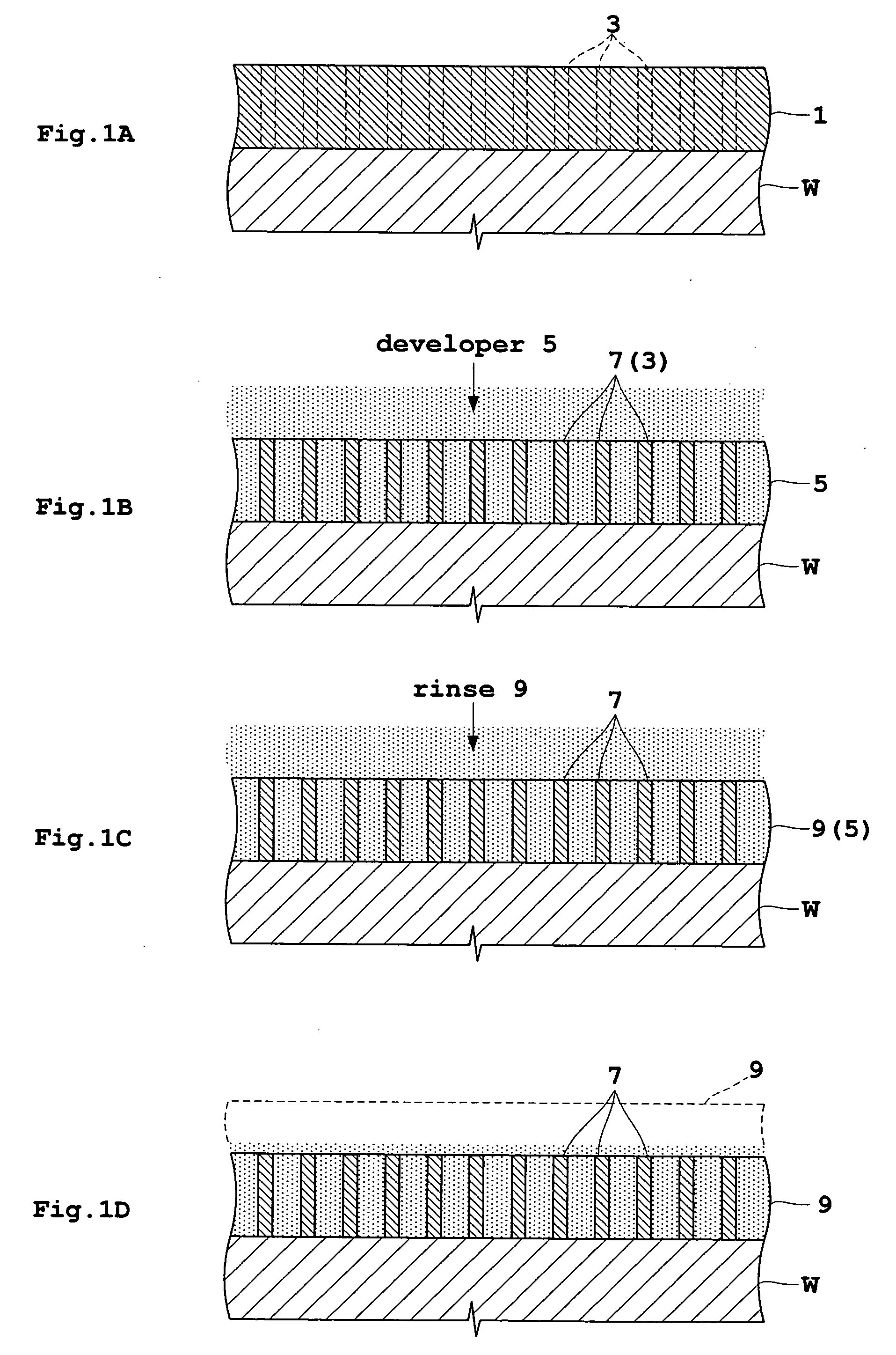
[0034]FIGS. 1 through 3 are views in vertical section of a substrate showing a process of treating the substrate by a pattern forming method in Embodiment 1.
[0035] A substrate or wafer W has a photosensitive film 1 formed on an upper surface thereof. The photosensitive film 1 is exposed through a mask having a predetermined pattern to form a latent image 3 corresponding to the predetermined pattern (FIG. 1A). The photosensitive film 1 is also called photoresist film, and is formed, for example, by using a spin coating apparatus (also called a spin coater).
[0036] When a developer 5 is supplied to the photosensitive film 1 on the wafer W and this state is maintained for a predetermined time, exposed portions of the photosensitive film 1 are dissolved by the developer, for example, and the latent image 3 forms a pattern 7 (FIG. 1B). In order to restrain a collapse of the pattern by liq...
embodiment 2
[0044] Embodiment 2 of this invention will be described hereinafter with reference to the drawings.
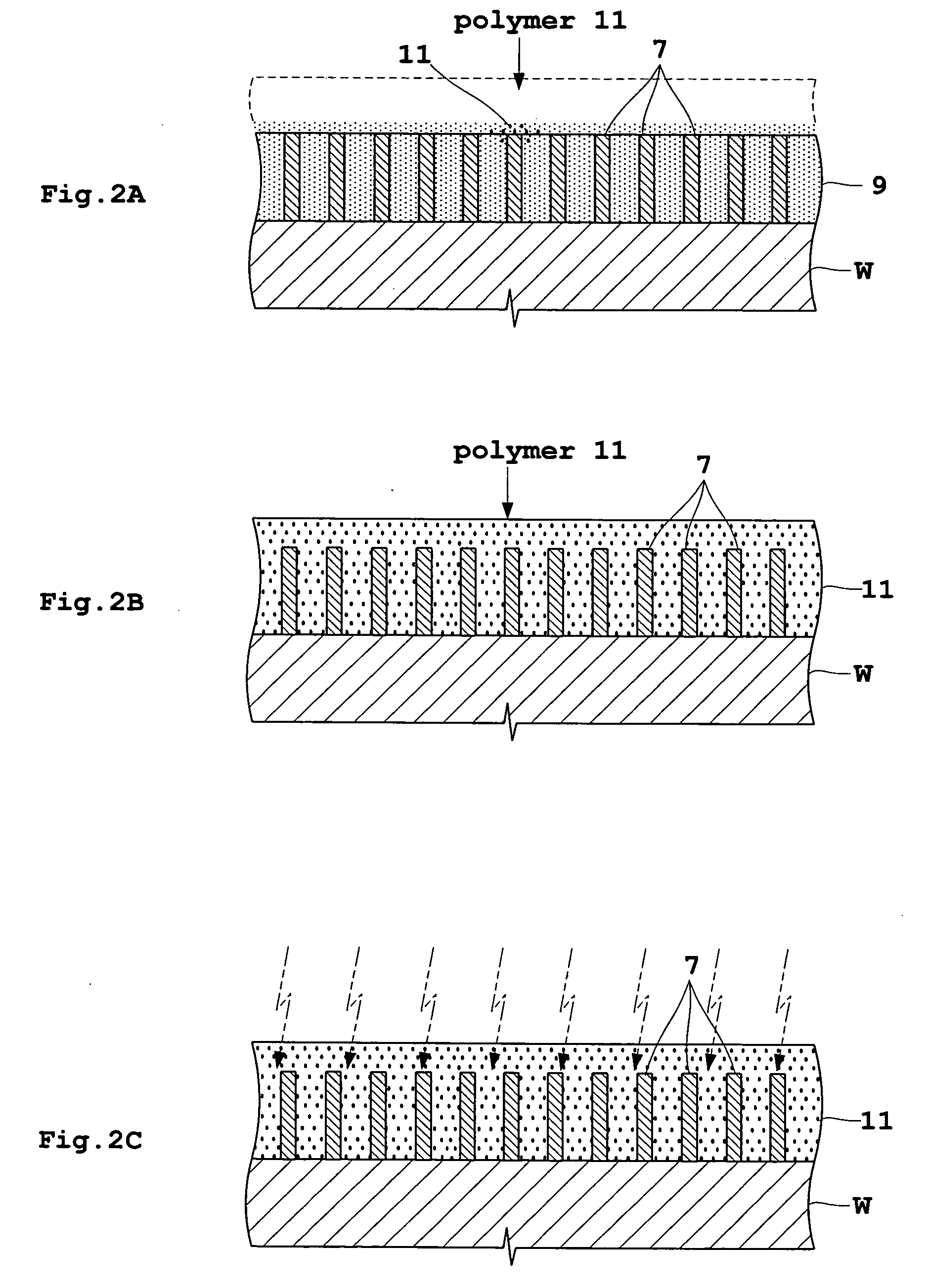
[0045]FIGS. 4 and 5 are views in vertical section of a substrate showing a process of treating the substrate by a pattern forming method in Embodiment 2. This embodiment is different from Embodiment 1 described above, in timing of supplying polymer 11.
[0046] A wafer W has a photosensitive film 1 formed thereon, and a latent image 3 corresponding to a predetermined pattern is formed on the photosensitive film 1 (FIG. 4A). Then, a developer 5 is supplied to form a pattern 7 (FIG. 4B). The developer 5 is replaced by a rinsing liquid 9 (FIG. 4C).
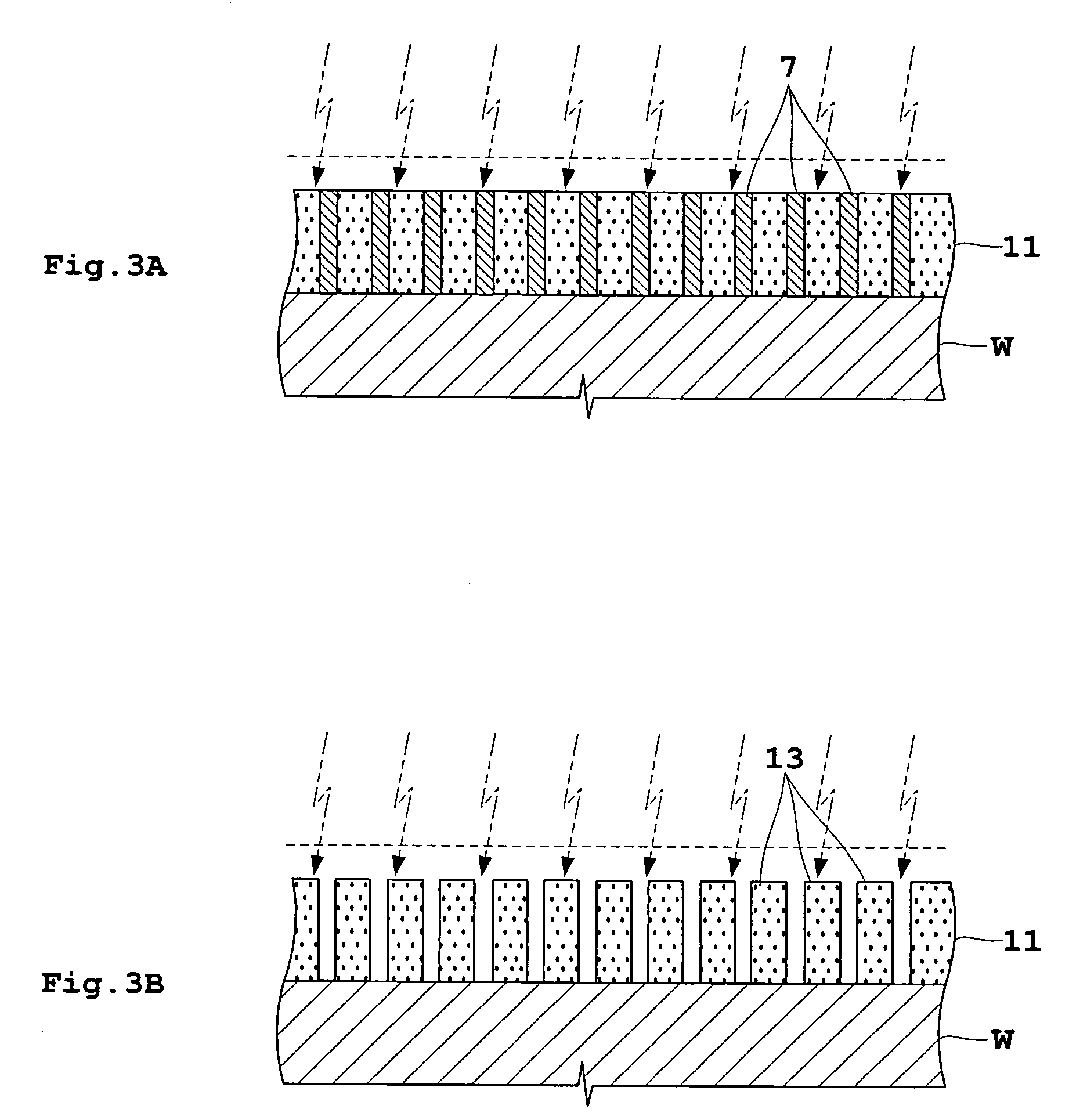
[0047] While maintaining the supply of rinsing liquid 9 for replacement, a polymer 11 is supplied (FIG. 4D). After stopping the supply of rinsing liquid 9, the supply of polymer 11 is stopped. As a result, the pattern 7 is covered by the polymer 11 (FIG. 5A).
[0048] After drying the polymer 11 covering the pattern 7, a dry etching process is per...
embodiment 3
[0050] Next, an apparatus suited for carrying out the above Embodiments 1 and 2 will be described as Embodiment 3 with reference to the drawings. FIG. 6 is a block diagram showing a film forming apparatus according to the invention. FIG. 7 is a view showing a dry etching apparatus according to the invention.
[0051] A film forming apparatus 21 forms a pattern 7 of coating film 1 on the upper surface of wafer W, and then forms a film of polymer 11 covering the pattern 7. A spin chuck 23 corresponding to the spin support device in this invention holds the wafer W in horizontal posture by sucking a center region on the lower surface of the wafer W. A rotary shaft 25 is connected to a lower part of the spin chuck 23, and is interlocked at a lower end thereof to a rotary shaft of a motor 27. The spin chuck 23 is surrounded by a vertically movable scatter preventive cup 29. The scatter preventive cup 29 has a function for downwardly guiding and collecting treating solutions such as the dev...
PUM
 Abstract
Description
Claims
Application Information
 - Generate Ideas
- Intellectual Property
- Life Sciences
- Materials
- Tech Scout
- Unparalleled Data Quality
- Higher Quality Content
- 60% Fewer Hallucinations
Browse by: Latest US Patents, China's latest patents, Technical Efficacy Thesaurus, Application Domain, Technology Topic, Popular Technical Reports.
© 2025 PatSnap. All rights reserved.Legal|Privacy policy|Modern Slavery Act Transparency Statement|Sitemap|About US| Contact US: help@patsnap.com