
Refrigeration cycle dehumidifier

a dehumidifier and refrigerant cycle technology, applied in the field of dehumidification systems, can solve the problems of vaporizing liquid and heat, and achieve the effects of improving the effectiveness of the system, reducing the superheating of the refrigerant vapor, and increasing the apparatus

Inactive Publication Date: 2007-01-18
SIMONS EVERETT
View PDF13 Cites 50 Cited by
  • Summary
  • Abstract
  • Description
  • Claims
  • Application Information

AI Technical Summary

Benefits of technology

[0017] An object of the present invention is to increase the effectiveness of apparatus that use the cold side of a compression-based refrigeration cycle (the evaporator) to draw condensate out of the air. The “effectiveness” is defined herein as the amount of condensation per unit time. It is a further object of the present invention to extend the range of conditions over which the apparatus can operate without being impeded by freezing of condensate onto the evaporator. Intermixing air streams of different temperatures without extracting energy from the process forever forfeits that energy; maintaining separation between the bypass air and the main air flow and reducing superheating of the refrigerant vapor improves the effectiveness of the system.
[0018] In one embodiment, improvement is achieved by directing the main flow of air through the evaporator and then through the middle and refrigerant outlet section of the condenser, while a bypass opening allows a bypass flow of air to be pulled in to cool the refrigerant inlet section of the condenser without first passing through the evaporator. The main air and the bypass air can be prevented from substantially intermixing prior to reaching the condenser. The air passing through the refrigerant outlet section of the evaporator can be directed to that part of the condenser through which refrigerant flows immediately after the refrigerant flows through that part of the condenser being cooled by the bypass air.
[0020] In certain embodiments, different sections of a heat exchanger along the refrigerant flow-path are thermally distinct; i.e., transfer heat to or from specific cross-sections of air flow; it can be more convenient if these cross-sections are compact. It can also be beneficial to minimize thermal conduction between different points along the refrigerant flow path of the heat exchanger, particularly between points that are not adjacent in the refrigerant flow-path sense.
[0021] An idealized example of a heat exchanger with every section thermally distinct would be a straight, low thermal conductivity tube (e.g. austenitic stainless steel), with high thermal conductivity fins (e.g. aluminum) perpendicular to the tube. In practice, copper tubing is often used because it is relatively easy to work with and any joints can be sealed reliably; spatial constraints usually require such a tube to be a serpentine coil, with substantially straight segments connected by alternating semicircular bends. Such a coil can still be considered to have thermally distinct sections, since each of these sections has a specific cross-section of air flowing through it. It can also be thermodynamically preferable, although not always mechanically practical, for the heat fins not to span more than one of these segments. The thermal conductivity of connections between non-adjacent sections of such a coil can be minimized, e.g. by using lower thermal conductivity material(s) for any required mechanical connections between non-adjacent sections.
[0024] Advantages of the present invention can be used in various ways, such as to increase the effectiveness of an existing system without other alteration, to downsize a given system while retaining the original effectiveness, or to regain some of the performance lost when an environmentally-questionable refrigerant is replaced by one that is safer but less thermodynamically efficient.

Problems solved by technology

Second, it takes heat to boil (vaporize) a liquid.

Method used


Image

  • Refrigeration cycle dehumidifier
  • Refrigeration cycle dehumidifier
  • Refrigeration cycle dehumidifier

Examples


Embodiment Construction

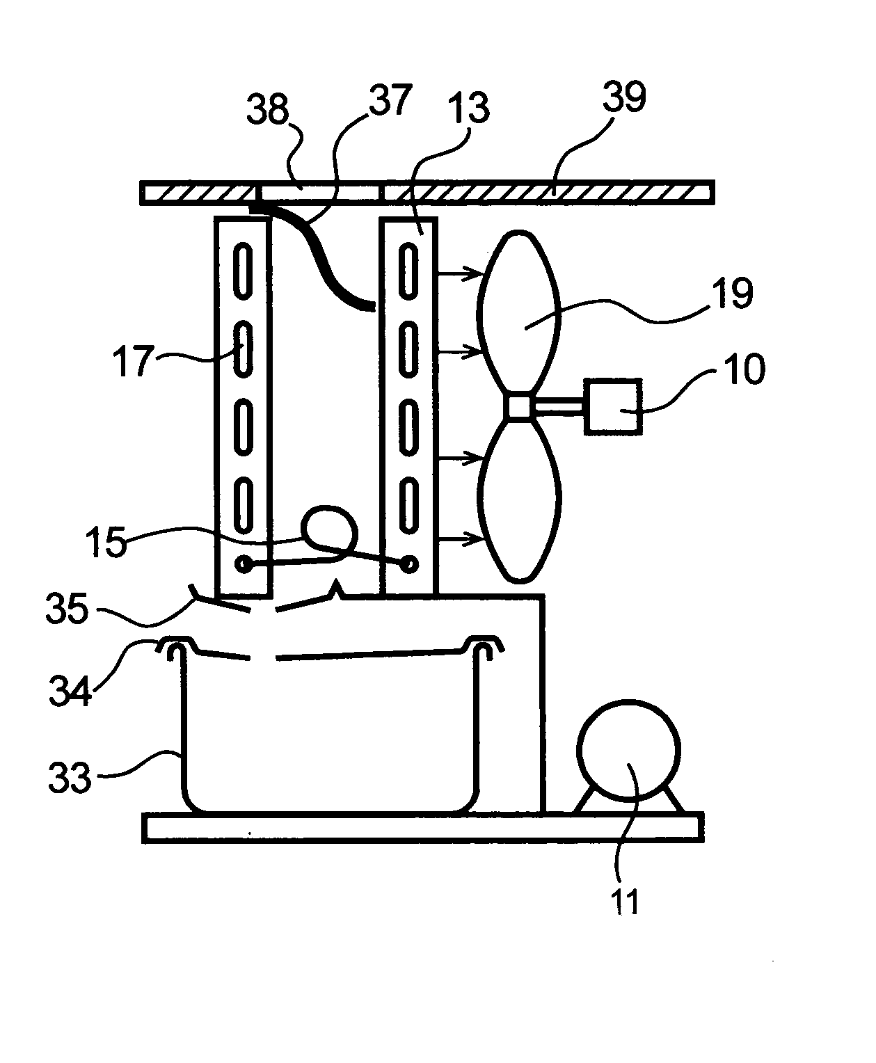
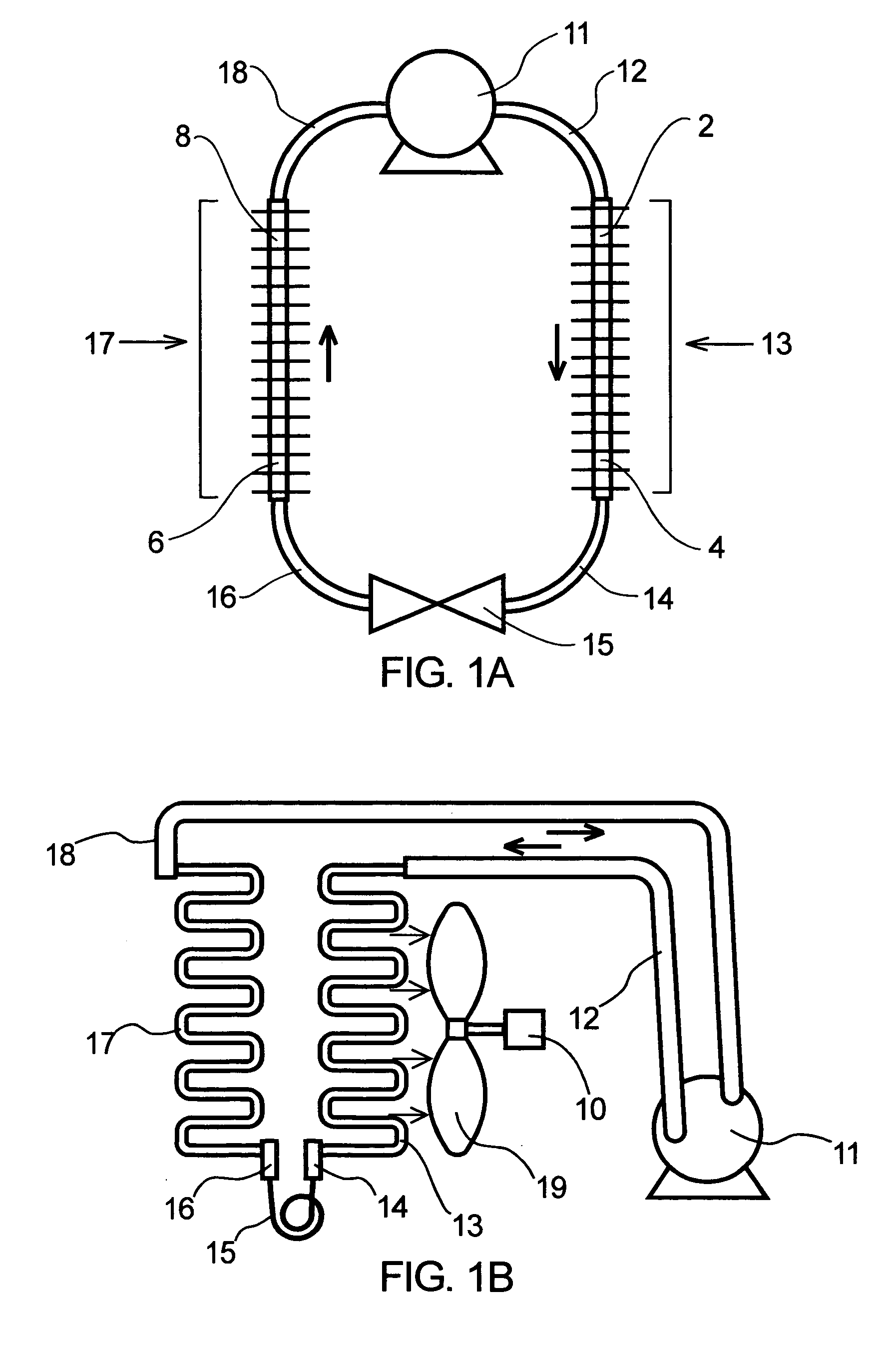
[0037]FIG. 1A is a schematic of a compression-based refrigeration cycle. A compressor 11 draws in cool, low-pressure refrigerant vapor from a tube 18 and mechanically compresses this refrigerant vapor. Adiabatic heating causes the temperature of the refrigerant vapor to rise as it is compressed. The refrigerant exits the compressor as a hot, high-pressure vapor, and flows through a tube 12 to a condenser 13.

[0038] Once in condenser 13, the refrigerant first flows through a condenser inlet section 2, the first section of condenser 13. As the refrigerant flows through condenser 13, the pressurized refrigerant vapor cools, and then condenses at an essentially constant temperature. The refrigerant can become entirely liquid and cool further within condenser 13. The refrigerant flows through a condenser outlet section 4, the last section of condenser 13, from which it exits through a tube 14 as a warm, pressurized liquid, possibly still containing some vapor phase.

[0039] This warm, hig...


PUM


Abstract

Methods and apparatus that improve the effectiveness of a compression-based refrigeration cycle dehumidifier by allocating thermally distinct sections of the condenser to different air flows are disclosed. A bypass opening and divider plate direct ambient air to the refrigerant inlet section of the condenser. Air that has been cooled and dehumidified by the evaporator is directed to the rest of the condenser, with the air from the refrigerant outlet section of the evaporator being preferentially directed downstream, in the refrigerant flow path sense, from that section of the condenser already allocated to the ambient air coming from the bypass opening. The flows of ambient air and dehumidified air can be adjusted to improve moisture removal rates and avoid blockage of the evaporator by freezing of the condensate onto the evaporator. The system may also be used to remove condensates other than water.

Description

BACKGROUND OF THE INVENTION [0001] 1. Field of the Invention [0002] The invention relates to dehumidification systems using a compression-based refrigeration cycle. [0003] 2. Description of Related Art [0004] The basic components of a compression-based refrigeration cycle are a compressor, a condenser, an expansion valve, an evaporator, and a refrigerant (a volatile liquid). Compression-based refrigeration cycles work because of a combination of physical laws common to all liquids. First, the temperature at which a liquid boils decreases as the ambient pressure decreases. Second, it takes heat to boil (vaporize) a liquid. A liquid vaporizing because of a reduction in ambient pressure absorbs heat from its surroundings; if the vapor is subsequently compressed enough to condense back to a liquid, it gives off heat as it condenses. [0005] A compressor, the active element in the cycle, forces refrigerant to circulate. A compressor pulls cool, low-pressure refrigerant vapor out of the ev...

Claims


Application Information

Patent Timeline
IPC IPC(8): F25D17/06F25D23/00F25D21/14
CPCF24F3/153F24F2003/1446F24F13/14
Inventor SIMONS, EVERETT
Owner SIMONS EVERETT
Features
  • Generate Ideas
  • Intellectual Property
  • Life Sciences
  • Materials
  • Tech Scout
  • Unparalleled Data Quality
  • Higher Quality Content
  • 60% Fewer Hallucinations
Learn More