Lamination stack cooling path

Inactive Publication Date: 2007-01-18
RELIANCE ELECTRIC TECH
View PDF29 Cites 56 Cited by
  • Summary
  • Abstract
  • Description
  • Claims
  • Application Information

AI Technical Summary

Benefits of technology

[0008] According to one embodiment, the present invention provides a lamination for an electric machine. The exemplary laminations are supported in a frame and cooperate with one another to form a lamination stack. Each exemplary lamination comprises a central aperture sized to receive a rotor, and a plurality of slots disposed circumferentially about the central aperture. These slots are configured to receive a plurality of windings. Additionally, the lamination comprises an outer periphery that defines a lamination cross-section such that the lamination is disposable in the frame. The outer periphery has at least one recessed section extending longitudinally between the ends of the lamination that is configured to cooperate with the frame to form a closed passageway for routing fluid. Accordingly, by routing fluid through the recessed sections of a plurality of laminations disposed within the frame, a mechanism for cooling the radially outward regions of the lamination stack that forms the stator is provided. Advantageously, cooling these outer regions of the stator improves the distribution of cooling resources. Additionally, to increase the efficacy of the cooling effect of the fluid, the recessed section of each lamination may be configured to cooperate with the frame and with adjacent laminations to form a labyrinthine passageway for routing the fluid along perimetric or peripheral surfaces of the assembled stator. Advantageously, the labyrinthine passageway provides a larger surface area of contact for the fluid while minimizing effects on structural integrity.
[0009] According to another exemplary embodiment, a lamination for a lamination stack is provided. The lamination includes a central aperture sized to receive a rotor and a plurality of slots disposed circumferentially about the central aperture at equiangular positions with respect to one another. Additionally, the lamination has an outer periphery that defines a generally circular lamination cross-section. The outer periphery also has at least one recessed section extending longitudinally between the ends of the lamination. The at least one recessed section is configured to cooperate with adjacent laminations of the stack to form a labyrinthine passageway extending along a circumferential surface of the lamination stack. Advantageously, a fluid may be routed through the labyrinthine passageway to dissipate heat developed in the lamination stack during operation of a motor, for example. As discussed above, the labyrinthine nature of the passageway creates a larger contact surface area for a cooling fluid routed through the passageway. Thus, the labyrinthine passageway facilitates more uniform cooling of the lamination stack and better dissipation of heat

Problems solved by technology

Indeed, the physical interaction of the devices various moving components produces heat by way of friction.
As yet another source of heat, ac magnetic fields lead to losses in the magnetic steel supporting the windings and conductors in the stator and rotor, respectively.
If left unabated, excess heat may degrade the performance of the device.
Worse yet, excess heat may contribute to any number of malfunctions, which may lead to system downtime and require maintenance.
Undeniably, reduced efficiency and malfunctions are undesirable events that may lead to increased costs.
Indeed, in traditional motors and generators, losses generated in the stator-whether in the conductors or in the magnetic steel-create heat in the stator that is typically dissipated by routing air or c

Method used


Image

  • Lamination stack cooling path
  • Lamination stack cooling path
  • Lamination stack cooling path

Examples


Example

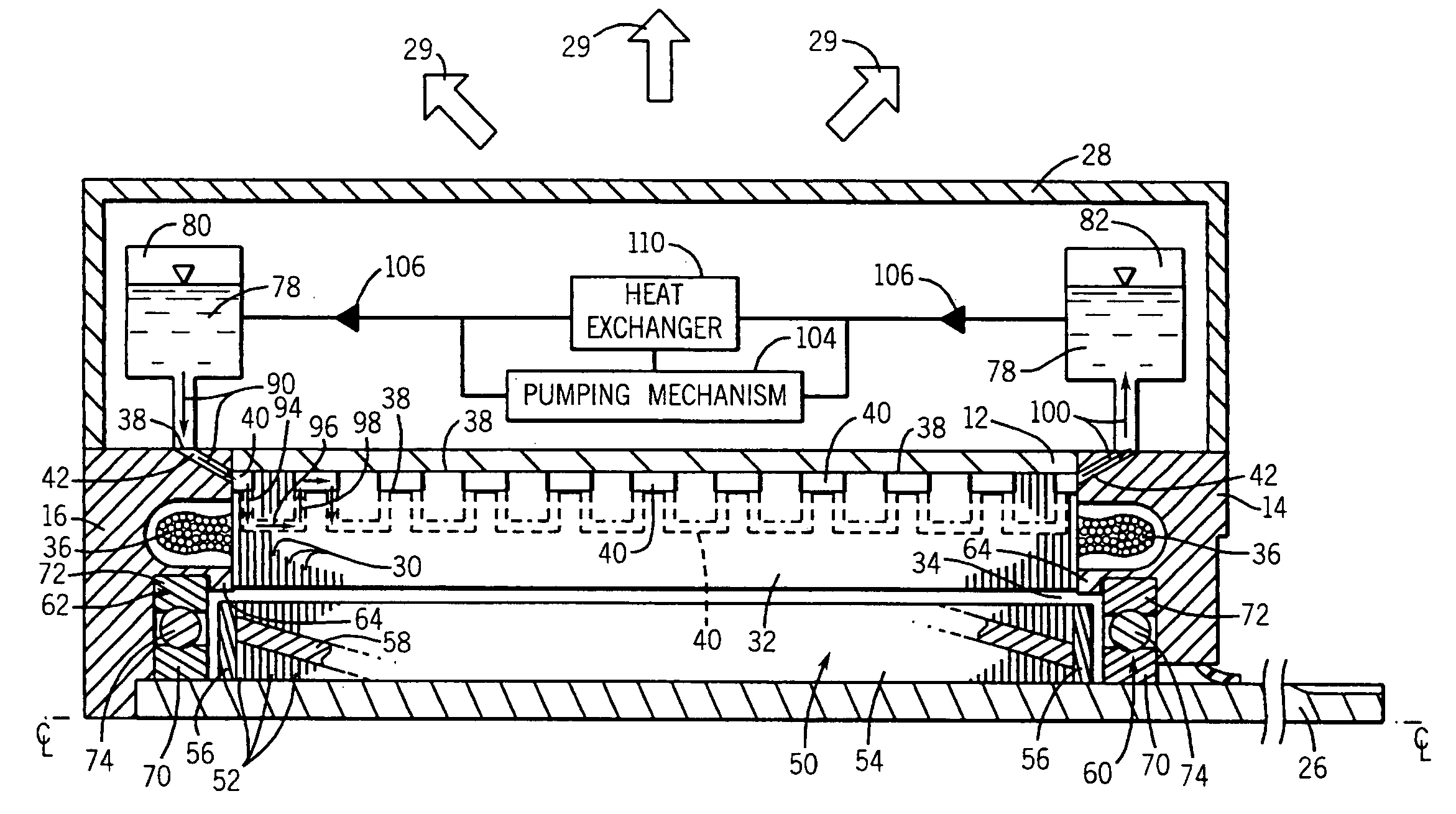
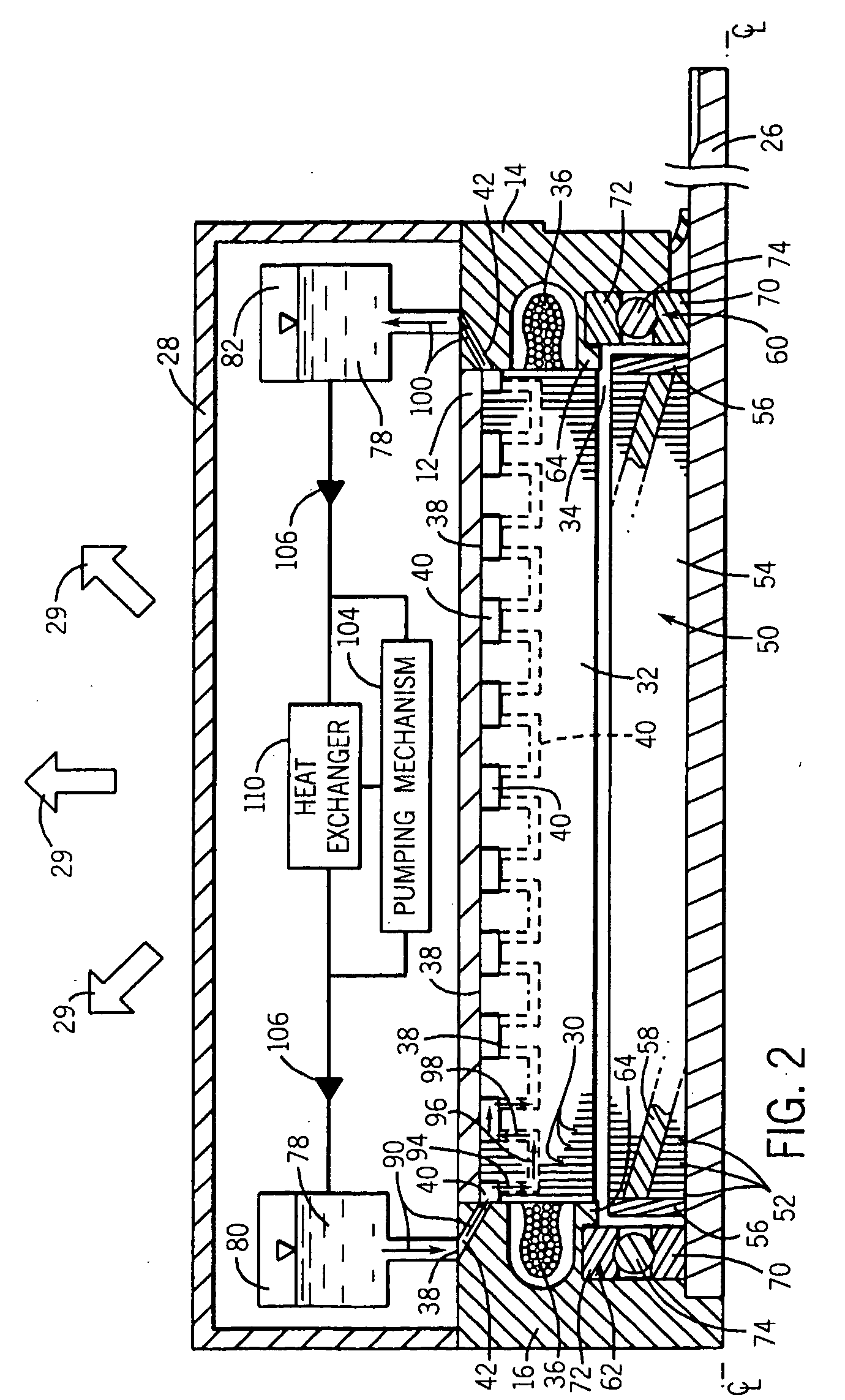
[0032] As discussed in detail below, embodiments of the present invention provide apparatus and methods for cooling electric machines having lamination stacks. Although the discussion regarding the present invention focuses on electric motors and generators, the present invention also affords benefits to a number of applications in which the cooling of a lamination stack is a concern. Accordingly, the following discussion relates to exemplary embodiments of the present invention and, as such, should not be viewed as limiting the appended claims to the embodiments described.

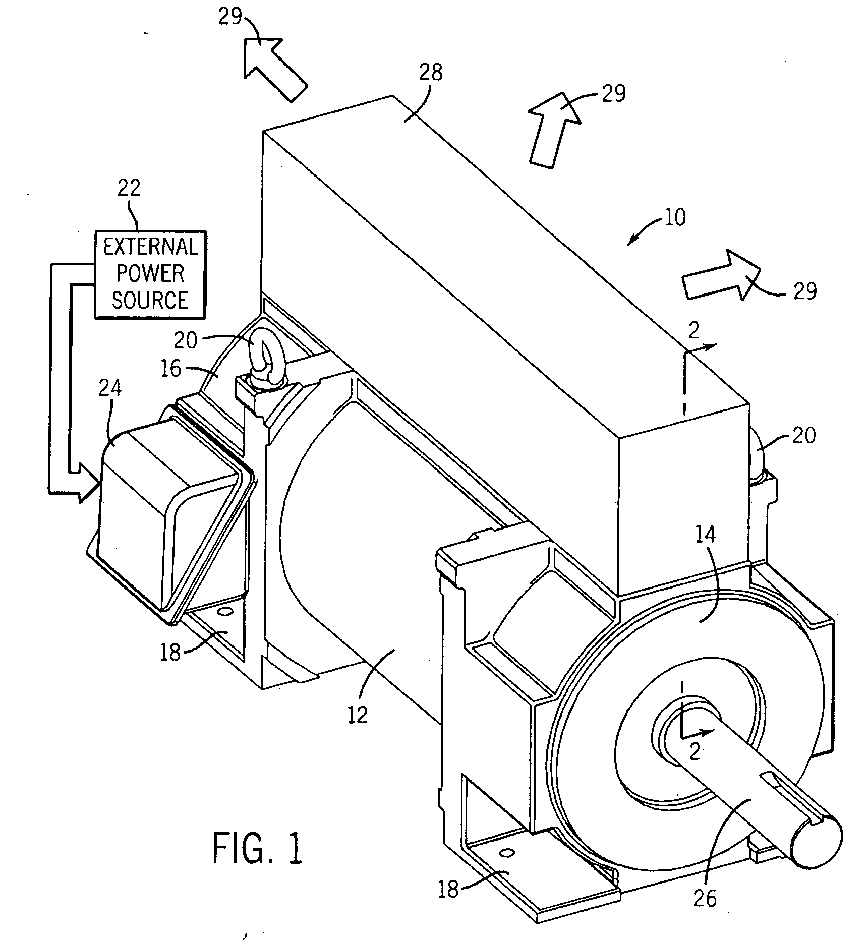
[0033] Turning to the drawings, FIG. 1 illustrates an exemplary electric motor 10. In the embodiment illustrated, the motor 10 comprises an induction motor housed in a motor housing. The exemplary motor 10 comprises a frame 12 capped at each end by drive-end and opposite drive-end endcaps 14 and 16, respectively. The frame 12 and the endcaps 14 and 16 cooperate to form the enclosure or motor housing for the motor...


PUM


Abstract

According to one embodiment, the present invention provides a motor having a stator core disposed in a motor frame. The stator core is formed of a plurality of substantially identical laminations. Each lamination of the stator core comprises at least one recessed section, which, in cooperation with the frame, defines an incremental segment of closed passageway for routing a fluid along a perimetric surface of the stator core. Accordingly, the closed passageway provides a mechanism by which the outer regions of the stator core may be more effectively cooled. Furthermore, the laminations of the stator core may be oriented at varied orientations with respect to one another to form a labyrinthine path along the surface of the stator core through which coolant is routed.

Description

BACKGROUND [0001] The present technique relates generally to the field of electric motors and generators, and to methods and apparatus for cooling such. For example, the present invention relates to a novel technique for dissipating heat in motors and generators by routing fluid along surfaces of a stator core. Although the present discussion focuses on electric motors and generators, the present invention affords benefits to a number of applications related to lamination stacks and to the cooling of such stacks. [0002] Electric motors and generators of various types are commonly found in industrial, commercial and consumer settings. In industry, motors are employed to drive various kinds of machinery, such as pumps, conveyors, compressors, fans and so forth, to mention only a few. Conversely, generators translate kinetic energy into electrical energy. Conventional alternating current electric (ac) motors and generators may be constructed for single or multiple phase power, and are ...

Claims


Application Information

Patent Timeline
IPC IPC(8): H02K9/20H02K9/00
CPCH02K1/32H02K15/024H02K9/19H02K9/197
Inventor SCHIFERL, RICH F.MELFI, MICHAEL J.DONG, QIMIN J.
Owner RELIANCE ELECTRIC TECH
Why Eureka
Try Eureka