Method, examination apparatus and antenna array for magnetic resonance data acquisition

Active Publication Date: 2007-01-18
SIEMENS HEALTHCARE GMBH
View PDF5 Cites 62 Cited by
  • Summary
  • Abstract
  • Description
  • Claims
  • Application Information

AI Technical Summary

Benefits of technology

[0011] In another embodiment, the frequency conversion ensues by means of an auxiliary radiation at an auxiliary frequency that lies in the microwave range, and is radiated onto the first antenna array and acquired thereby. To reduce the interference, the auxiliary radiation can be radiated at a phase-modulated and/or frequency-modulated auxiliary frequency, with the modulation in the signals being cancelled by analog or digital means.
[0012] A circularly-polarized auxiliary radiation has the advantage of making the transmission insensitive to relative rotations of the antenna elements.
[0013] In a preferred embodiment of the method, the acquired MR signals with the auxiliary radiation are linearly converted in the frequency converters into frequency-converted signals that differ from the auxiliary frequency by the MR frequency.
[0014] In a further embodiment of the method, the antenna elemen

Problems solved by technology

The cables and the necessary plug contacts represent a limitation to the user-friendli

Method used


Image

  • Method, examination apparatus and antenna array for magnetic resonance data acquisition
  • Method, examination apparatus and antenna array for magnetic resonance data acquisition
  • Method, examination apparatus and antenna array for magnetic resonance data acquisition

Examples


Embodiment Construction

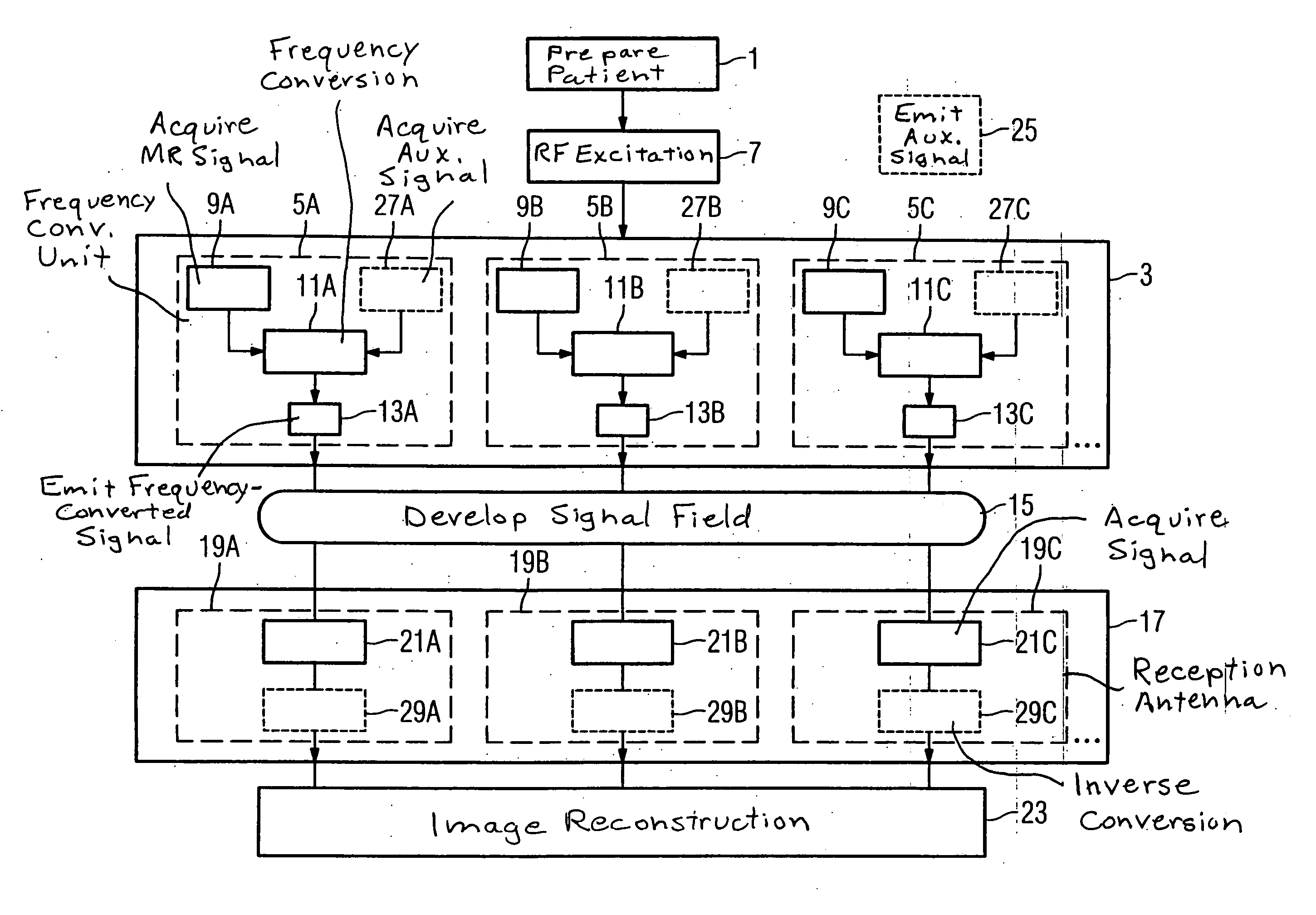
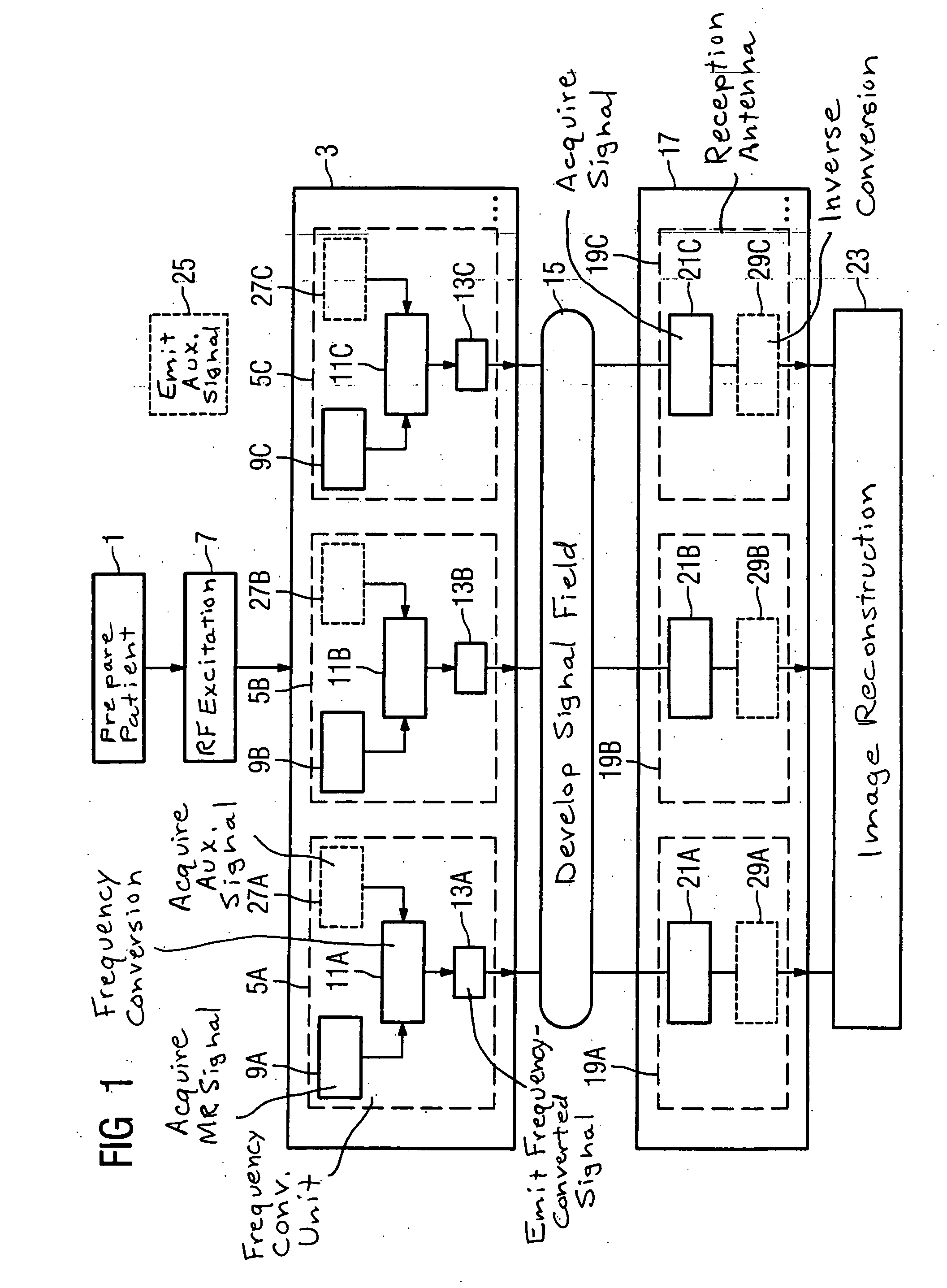
[0033] In an exemplary flowchart, FIG. 1 illustrates an embodiment of the method for implementation of an MR examination with an MR apparatus in accordance with the invention. In step 1, a patient is prepared for MR examination, meaning that the patient is positioned on a patient bed of the MR apparatus and an array 3 of frequency conversion units 5A, 5B, 5C, . . . to be used is arranged corresponding to a region of the patient to be examined. The frequency conversion units 5A, . . . serve for the acquisition of spatially resolved MR signals. If the preparation is concluded, the patient is inserted into the examination region of the MR apparatus, meaning the region to be examined is positioned in the isocenter of the basic magnetic field for the MR examination. The RF excitation 7 that excites the MR signals in the examination region now ensues. For the acquisition steps 9A, 9B, 9C . . . of the MR signals, the frequency conversion units 5A, . . . are, for example, arranged in a lami...


PUM


Abstract

In a method for implementation of a magnetic resonance examination, and a magnetic resonance apparatus, and an array for acquisition of magnetic resonance signals, and a magnetic resonance signal at a magnetic resonance frequency are acquired from an examination region with an array of frequency conversion units after an RF excitation and are radiated as frequency-converted signals. The resulting signal field is acquired by a number of reception antennas of a second antenna array, which are arranged at different spatial positions and thus allow a spatial resolution of the frequency-converted signals. The acquired acquisition signals are used for image reconstruction.

Description

BACKGROUND OF THE INVENTION [0001] 1. Field of the Invention [0002] The present invention concerns a method for implementation of a magnetic resonance examination (MR examination) with an MR apparatus, of the type wherein MR signals with an MR frequency are acquired from an examination region with an antenna array after a radio-frequency excitation (RF excitation). The invention furthermore concerns a magnetic resonance apparatus and an antenna array for acquisition of magnetic resonance signals. [0003] 2. Description of the Prior Art [0004] MR examinations enable spatially-resolved imaging of an examination region. For reasons of the achievable signal-to-noise ratio, in MR apparatuses it is advantageous to use local or surface coils for acquisition of MR signals from only a limited small region of the subject. Such coils are normally connected with an evaluation device via cables. The cables and the necessary plug contacts represent a limitation to the user-friendliness and the rel...

Claims


Application Information

Patent Timeline
IPC IPC(8): G01V3/00
CPCA61B5/055H03F7/04G01R33/3692G01R33/3415
Inventor HEID, OLIVERVESTER, MARKUS
Owner SIEMENS HEALTHCARE GMBH
Why Eureka
Try Eureka