Source driver and internal data transmission method thereof

Active Publication Date: 2007-01-18
NOVATEK MICROELECTRONICS CORP
View PDF4 Cites 17 Cited by
  • Summary
  • Abstract
  • Description
  • Claims
  • Application Information

AI Technical Summary

Benefits of technology

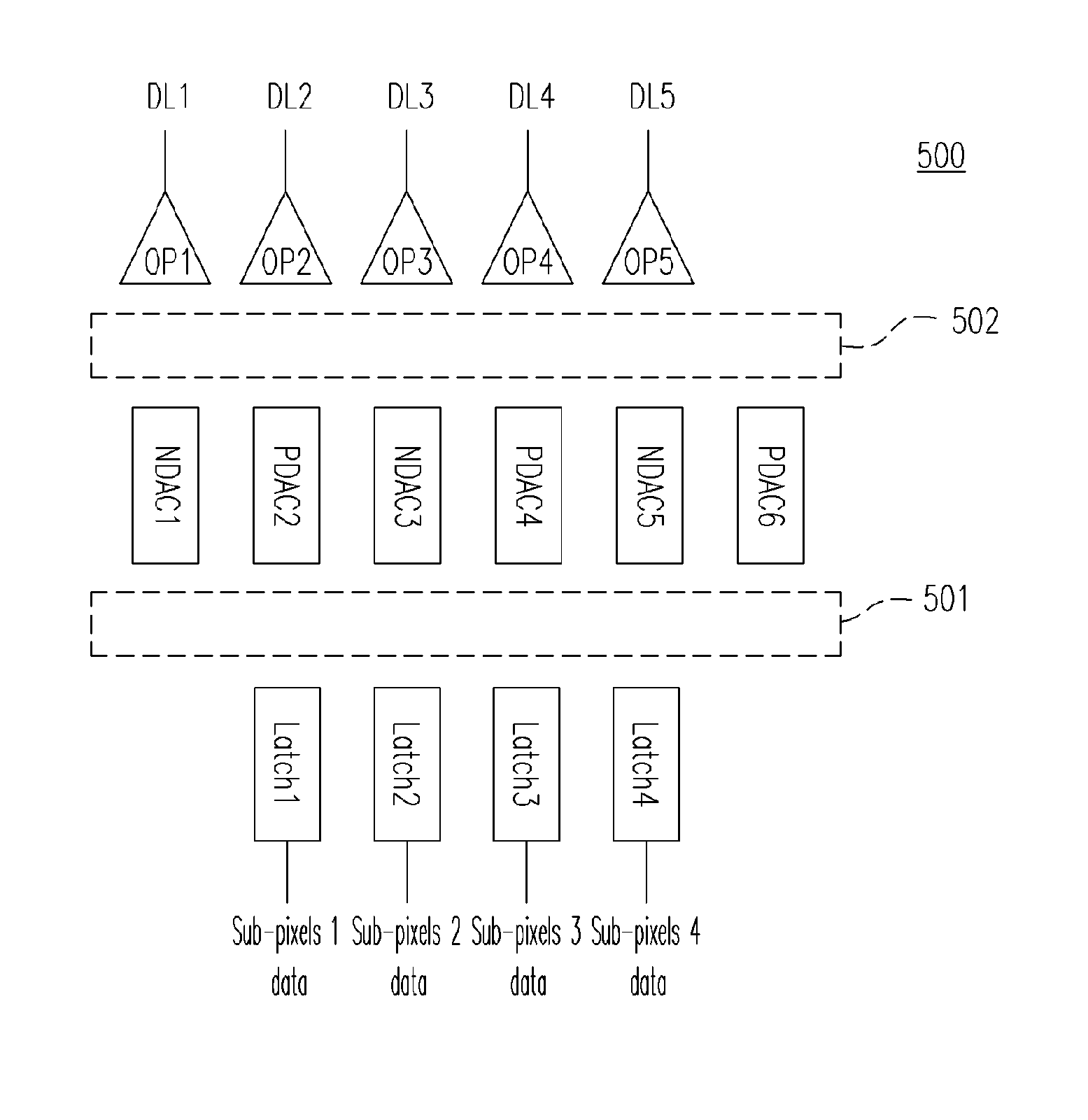
[0020] According to the aforementioned embodiment of the present invention, the present invention employs specially designed switch units and creates specially designed data paths in a source driver, and in combination with specially fabricated pixel array for allowing the data signals to be transmitted to the corresponding sub-pixels. When driving with a dot inversion driving method and within the duration of a single frame, a single output buffer is able to continuously output voltages of positive polarity and voltages of negative polarity, instead of switching between positive and negative polari

Problems solved by technology

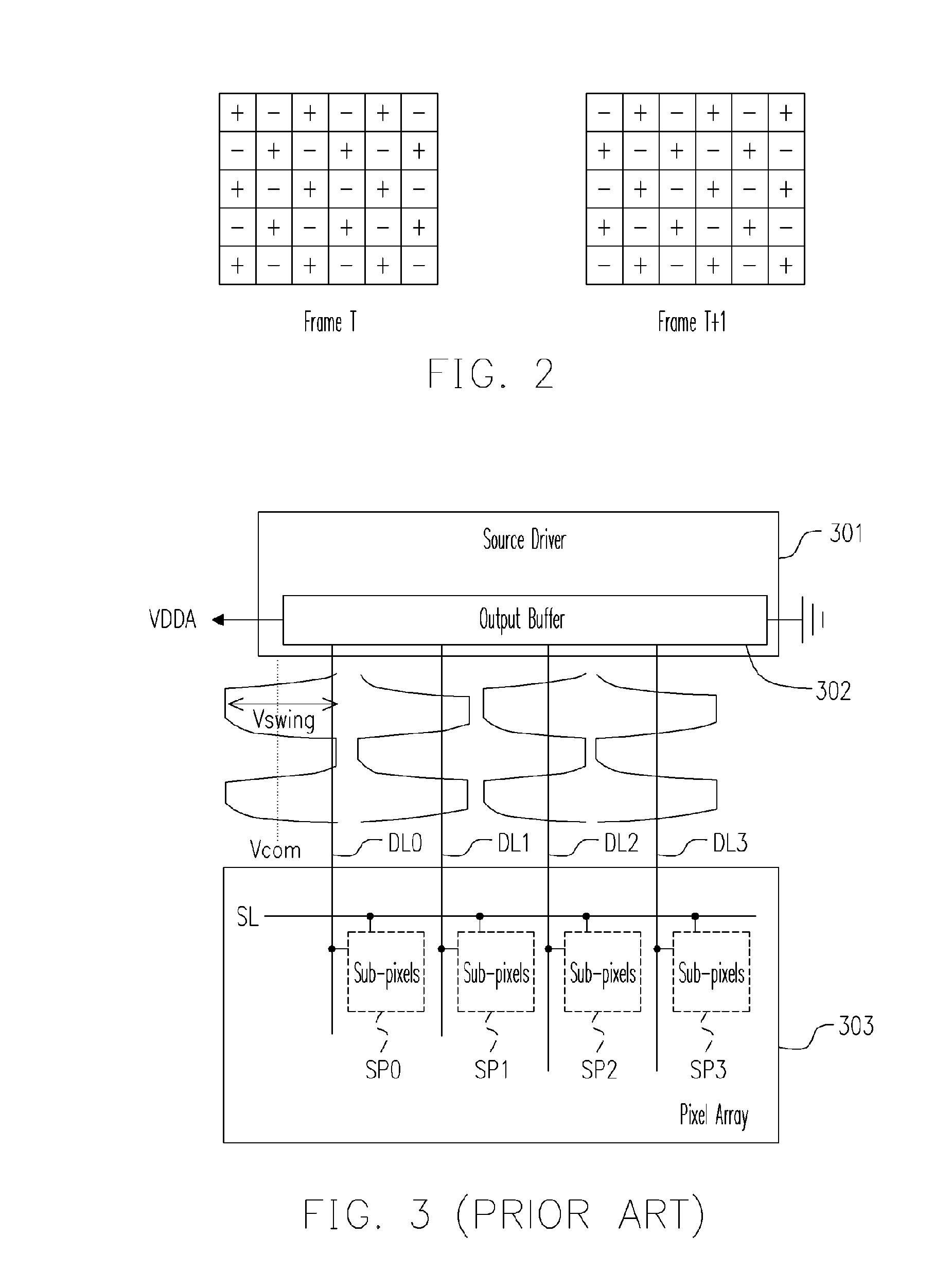
Although a dot inversion driving method has many advantages, it unfortunately consumes relatively more power than others.
The higher the Vswing, the more the power consumption becomes.
Thus the disadvantage of power consumption of the dot inversion driving method becomes even more apparent.
In addition, another disadvantage of the conventional technology is that the DAC has to output voltages of both positive polarity and negative polarity.
Being

Method used


Image

  • Source driver and internal data transmission method thereof
  • Source driver and internal data transmission method thereof
  • Source driver and internal data transmission method thereof

Examples


Embodiment Construction

[0029] The present invention is adapted for operating in accordance with a specially designed pixel array. Referring to FIG. 4, it illustrates a pixel array 400 according to an embodiment of the invention and the driving polarities of a plurality of sub-pixels when using a dot inversion driving method. The pixel array 400 includes six scan lines, SL0 through SL5, and five data lines, DL1 through DL5. Each scan line has four sub-pixels, which are marked with circles and labeled as 1 through 4, in which the symbol “+” represents positive driving polarity and the symbol “−” represents negative driving polarity. As illustrated in FIG. 4, during a certain frame “T”, the driving polarity of a sub-pixel 1 of the scan line SL0 is negative, and during the next frame “T+1”, the driving polarity of the sub-pixel 1 of the scan line SL0 is positive.

[0030] It should be noted that the pixel array 400 is described herein for illustrative purposes only, and the quantities of either the data lines o...


PUM


Abstract

A source driver and an internal data transmission method are provided. The present invention employs specially designed switch units and creates specially designed data paths in a source driver, which matches with the driving method for dot invesion and the specially designed pixel array. When the dot inversion driving method is used on a pixel array of a specific design, each output buffer and digital-to-analog converter inside the source driver continuously output voltages of positive polarity and voltages of negative polarity, instead of switching between positive and negative polarities. Consequently, the swing voltages that the source driver outputs can be lowered, the power consumption can also be reduced accordingly, a smaller area is occupied, and the costs are reduced.

Description

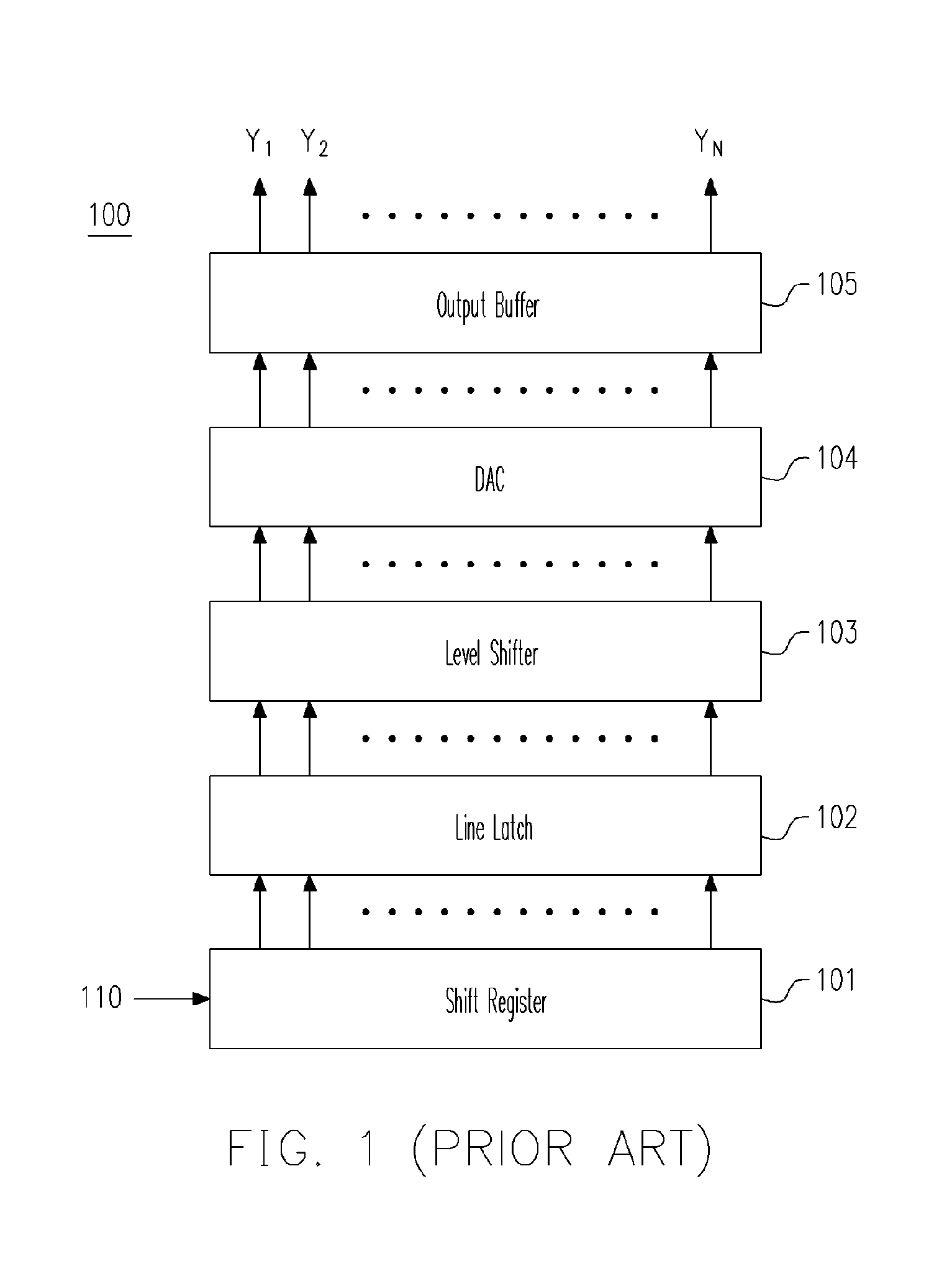
CROSS-REFERENCE TO RELATED APPLICATION [0001] This application claims the priority benefit of Taiwan application serial no. 94123506, filed on Jul. 12, 2005. All disclosure of the Taiwan application is incorporated herein by reference. BACKGROUND OF THE INVENTION [0002] 1. Field of the Invention [0003] The present invention relates to a source driver and an internal data transmission method thereof, and more particularly to a source driver and an internal data transmission method adapted for use with a dot inversion driving method. [0004] 2. Description of Related Art [0005] As an important component of a thin film transistor liquid crystal display (TFT-LCD), a source driver is responsible for converting the digital signals required for image displaying into analog signals and outputting the converted signals to every sub-pixel, also referred to as a dot, of a TFT-LCD. [0006]FIG. 1 is a structural block diagram of a conventional source driver 100. Referring to FIG. 1, a conventional...

Claims


Application Information

Patent Timeline
IPC IPC(8): G09G3/36
CPCG09G3/3614G09G2330/021G09G2310/0297G09G3/3688
Inventor LIN, CHE-LICHEN, CHANG-SAN
Owner NOVATEK MICROELECTRONICS CORP
Why Eureka
Try Eureka