Substrate carrier

a carrier and substrate technology, applied in the direction of thin material handling, cleaning process and apparatus, cleaning using liquids, etc., can solve the problems of limiting the efficiency of increasing the carriage efficiency of the substrate, the movement of each of the carrier arms is limited, etc., to improve the efficiency of the carriage of the substrate, improve the throughput, and simplify the control of the movement of the carrier arms

Inactive Publication Date: 2007-01-25
TOKYO ELECTRON LTD
View PDF14 Cites 15 Cited by
  • Summary
  • Abstract
  • Description
  • Claims
  • Application Information

AI Technical Summary

Benefits of technology

[0017] According to the present invention, the degrees of freedom of movements of the carrier arms are increased to improve the substrate carriage efficiency, resulting in an improved throughput. Further, the control of the movements of the carrier arms can be simplified.

Problems solved by technology

However, since the above-described conventional substrate carrier has a plurality of arms placed one above the other in the vertical direction, and the carrier arms are moved in the vertical direction as one body, the movement of each of the carrier arms is limited by the movement of the other carrier arm.
Furthermore, there is a limit to increasing the substrate carriage efficiency.

Method used


Image

  • Substrate carrier
  • Substrate carrier
  • Substrate carrier

Examples


Embodiment Construction

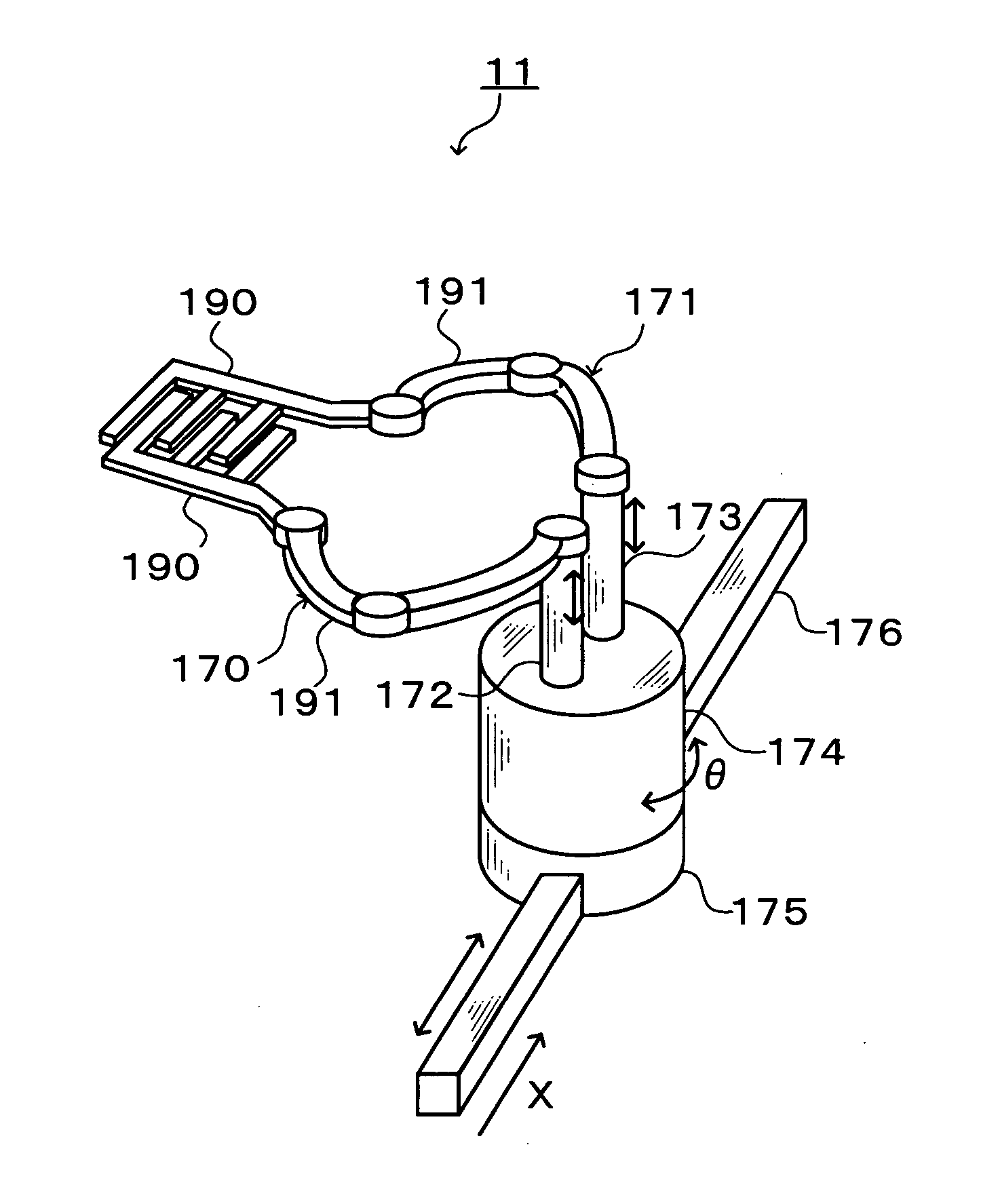
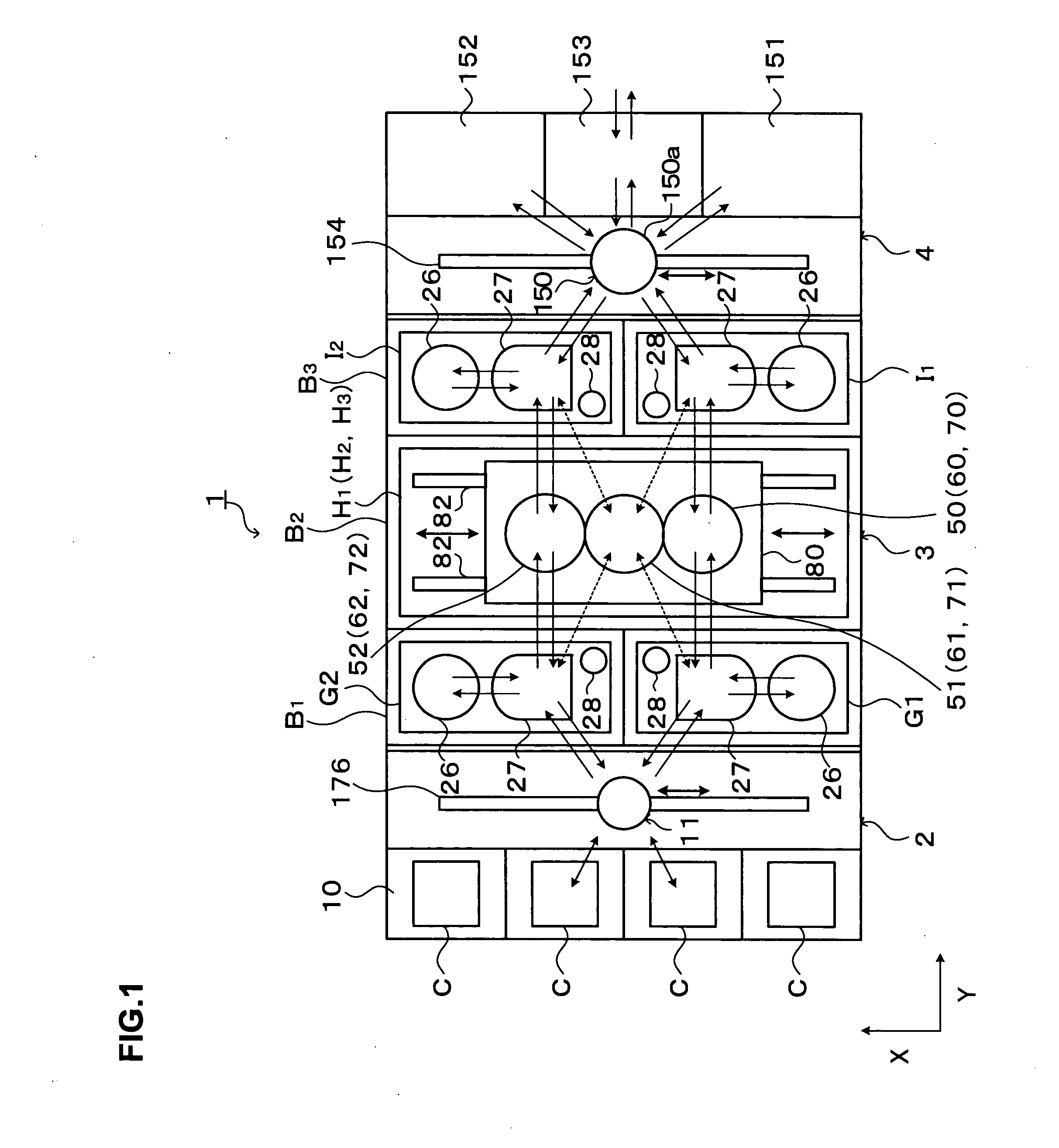
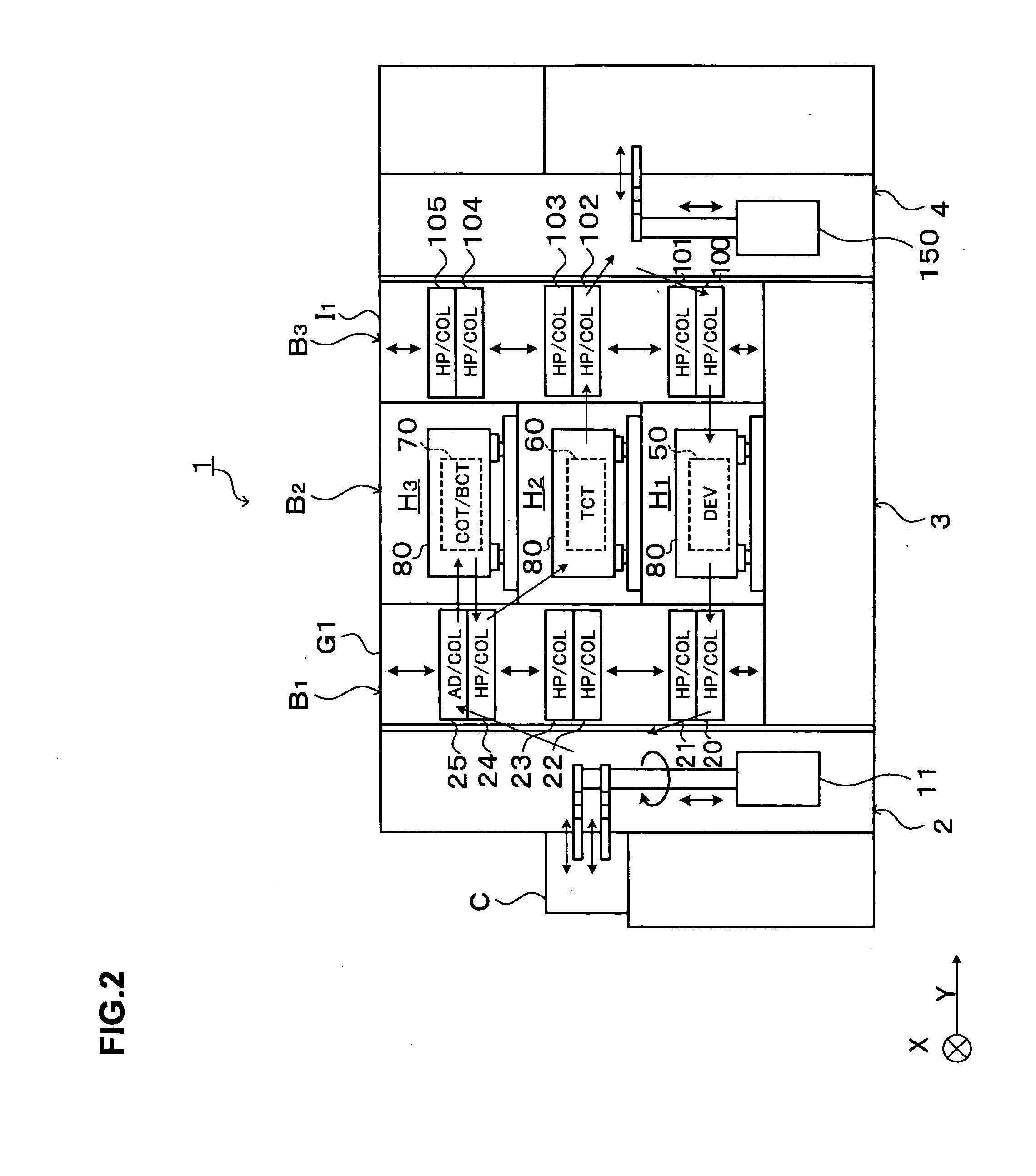
[0030] Hereinafter, a preferred embodiment of the present invention will be described. FIG. 1 is a plan view showing the outline of a configuration of a substrate processing system 1 equipped with a substrate carrier according to this embodiment.

[0031] The substrate processing system 1 has, as shown in FIG. 1, a configuration in which, for example, a cassette station 2 for carrying, for example, 25 wafers W per cassette as a unit from / to the outside into / from the substrate processing system 1 and carrying the wafers W into / out of cassettes C; a processing station 3 provided adjacent to the cassette station 2 and including a plurality of units for performing various kinds of processing or treatments in the photolithography process; and an interface section 4 for transferring the wafers W to / from an aligner (not shown) provided adjacent to the processing station 3, are integrally connected together. The cassette station 2, the processing station 3, and the interface section 4 are con...


PUM


Abstract

The present invention includes a plurality of carrier arms provided close to each other, each of the carrier arms for supporting a substrate and carrying the substrate in the horizontal direction. The plurality of carrier arms are arranged such that carriage paths thereof overlap one on the other in plan view, each of the paths for carrying-in/out the substrate to/from a processing unit or a substrate housing cassette, and each of the plurality of carrier arms is independently movable in the vertical direction and is capable of passing the other in the vertical direction without interfering with each other. According to the present invention, in the carrier including the plurality of carrier arms, the degrees of freedom of the carrier arms are increased to improve the substrate carriage efficiency.

Description

BACKGROUND OF THE INVENTION [0001] 1. Field of the Invention [0002] The present invention relates to a substrate carrier. [0003] 2. Description of the Related Art [0004] In a photolithography process, for example, in a manufacturing process of a semiconductor device, a plurality of treatments and processing are continuously performed such as a resist coating treatment of applying a resist solution to a substrate such as a wafer, a developing treatment of developing the substrate after exposure, thermal processing of heating and cooling the substrate, and so on. [0005] In the above-described plurality of treatments and processing are generally performed in a coating and developing treatment system. The coating and developing treatment system includes, for example, a cassette station in which cassettes each capable of housing a plurality of substrates are mounted; a processing station in which various kinds of treatment and processing units are arranged which perform the resist coatin...

Claims


Application Information

Patent Timeline
Patent Type & Authority Applications(United States)
IPC IPC(8): B08B3/00
CPCH01L21/67742H01L21/67276H01L21/67766H01L21/67778H01L21/6779H01L21/68707Y10S414/141
Inventor KIYOTA, KENJI
Owner TOKYO ELECTRON LTD
Why Eureka
Try Eureka