System and method for laser machining

a laser machining and laser technology, applied in the field of laser machining, can solve the problems of affecting the resolution of the features that are machined, affecting the quality of the finished product, and certain types of materials may be more difficult to machine with lasers

Active Publication Date: 2007-01-25
IPG PHOTONICS CORP
View PDF36 Cites 40 Cited by
  • Summary
  • Abstract
  • Description
  • Claims
  • Application Information

AI Technical Summary

Problems solved by technology

Some structures, such as biomedical devices, may be difficult to machine using a laser because of the material and / or the shape of the structure.
Residual heat penetration during ablation may affect the resolution of the features that are machined.
Certain types of materials may be more difficult to machine with lasers than others.
Sensitive materials are normally not easily processed at longer wavelengths (e.g., at 248 nm) due to optical and thermal effects.
Sensitive material may also have a relatively low thermal capacity and / or low melting point, i.e., it will melt and deform with low heat input (or low power density).
When a laser is used to machine thermally sensitive polymers, the material surrounding the area being machined has a tendency to melt or deform under laser irradiation.
The longer absorption depth coupled with the higher required ablation threshold energy density may result in a larger etch depth per laser pulse and may also result in a larger residual heat which consequently remains in the material adjacent to the etch zone after ablation.
Thus, a 248 nm laser may provide advantages in laser machining applications but may have drawbacks when used to machine sensitive materials.
In particular, the achievable resolution may be limited due to the melting effects.
However, this limits the effective processing speed for the sensitive materials and therefore limits the economics for high volume production applications.
Thus, a fast scanning speed of the workpiece under a laser beam can reduce the effective, local power density delivered to that workpiece.
When using fast scanning speeds, however, the ability to -image complex non-repeating features over a large area may be difficult due to the optics required to image a large area with high optical resolution.
Machining complex patterns may be even more difficult on certain shapes, such as a curved surface on a cylindrical structure.

Method used


Image

  • System and method for laser machining
  • System and method for laser machining
  • System and method for laser machining

Examples


Embodiment Construction

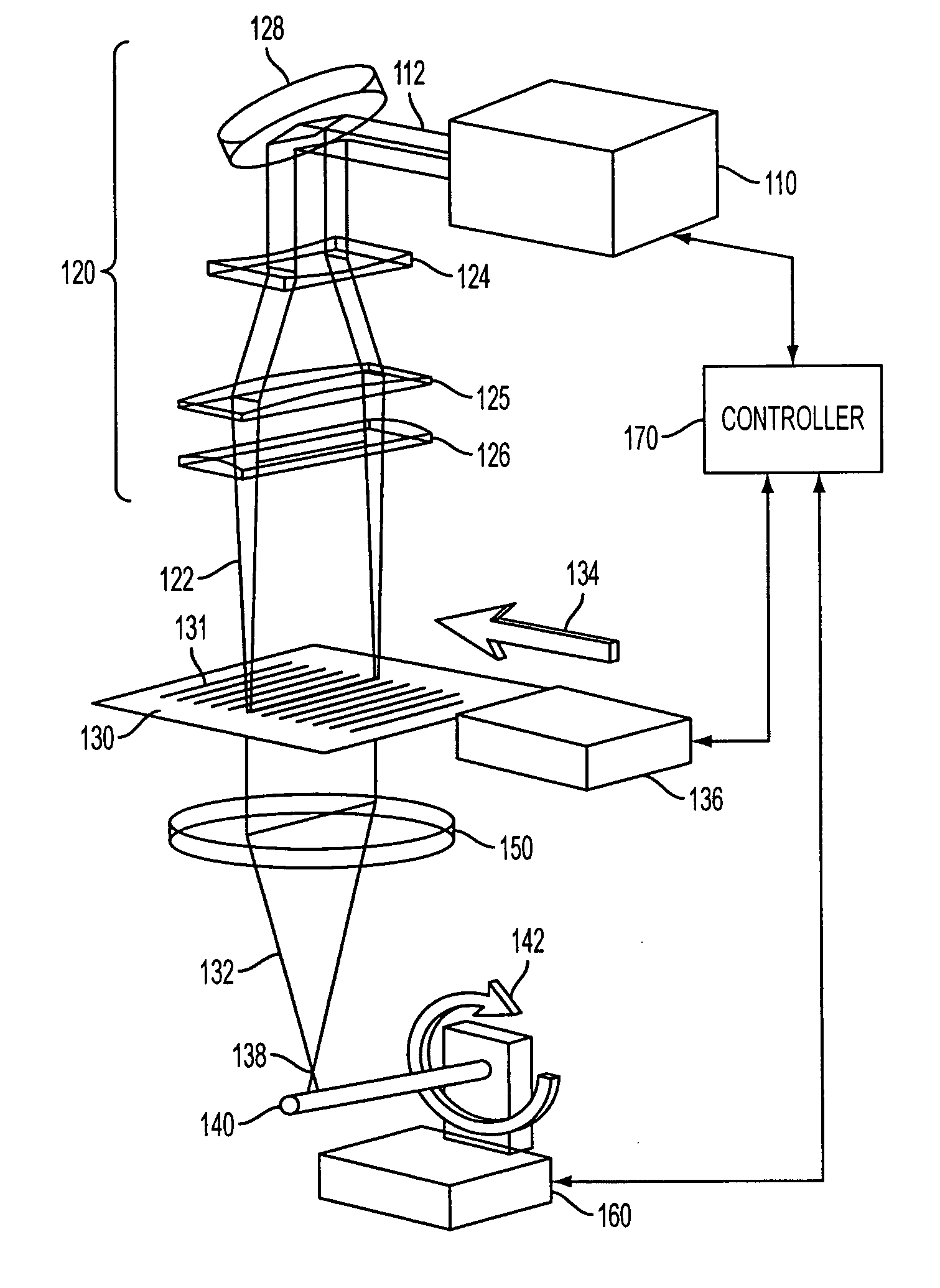
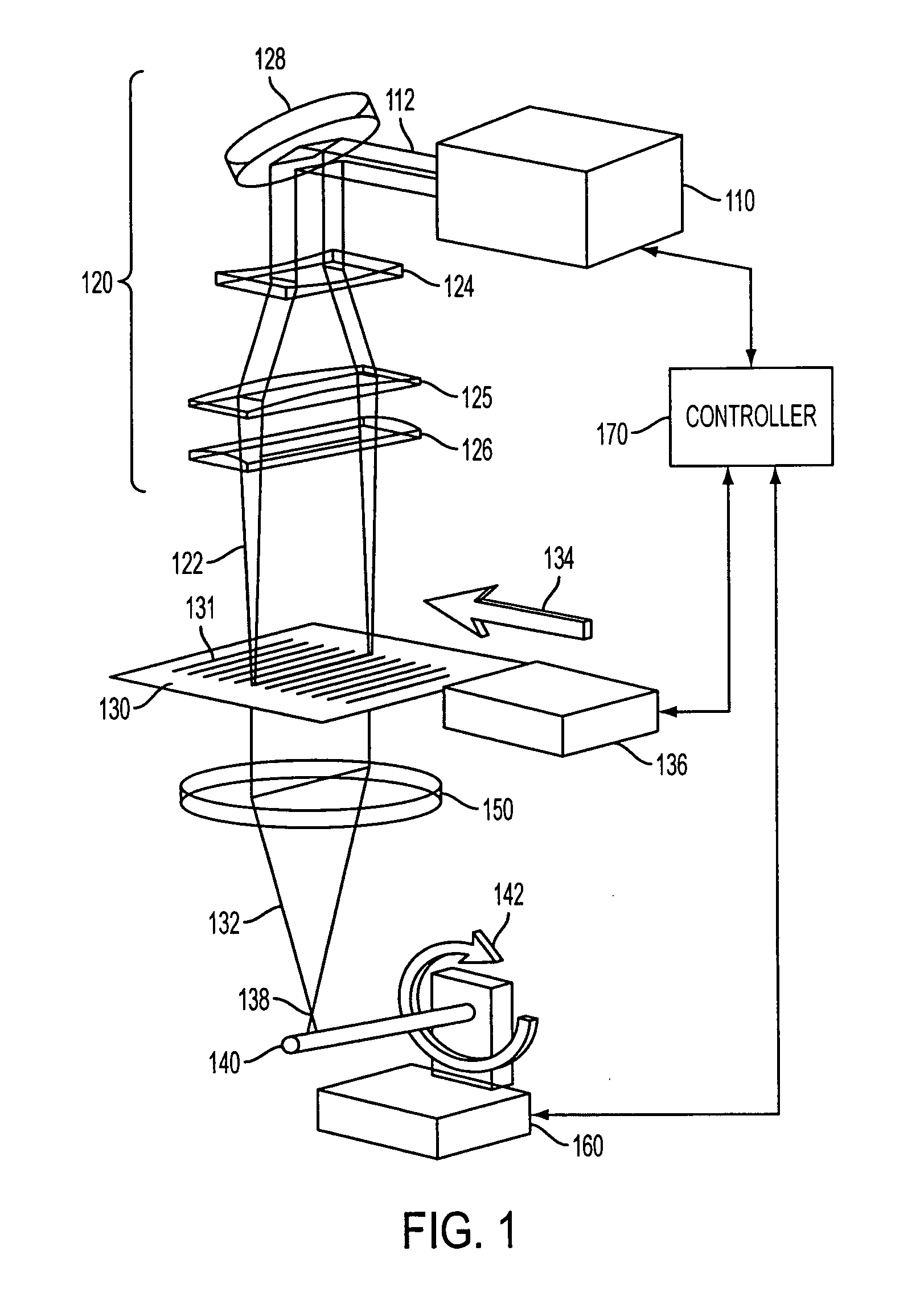
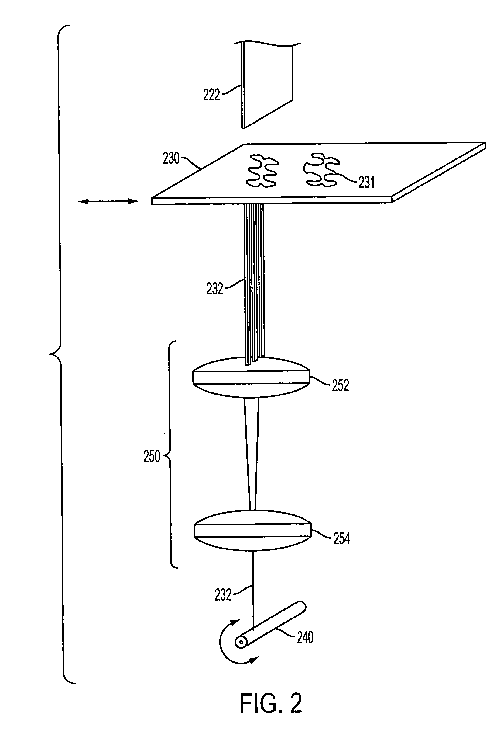
[0016] In general, a laser machining system and method, consistent with embodiments of the present invention, uses a shaped laser beam, such as a long, narrow beam, and scans the beam across a mask having an aperture pattern. The pattern on the mask is imaged onto a workpiece and the patterned laser beam selectively removes material from the workpiece. The laser may use a longer wavelength (e.g., 248 nm) and the beam may be scanned at a high rate of speed to reduce the dissipation of the residual thermal energy in the material, as will be described in greater detail below.

[0017] In one application, an exemplary system and method may be used to machine a complex pattern with relatively high resolution and high speeds into a curved surface of a rotating workpiece using a technique referred to as rotational coordinated opposing motion (COMO). The workpiece in the exemplary application may be made of a sensitive material. As used herein, sensitive material refers to a material that has...


PUM

PropertyMeasurementUnit
wavelengthaaaaaaaaaa

Abstract

A laser machining system and method uses a shaped laser beam, such as a long, narrow beam, and effectively scans the beam in the narrow direction across a mask having an aperture pattern. The pattern on the mask is imaged onto a moving workpiece and the patterned laser beam selectively removes material from the workpiece. The workpiece may be moved using a coordinated synchronized rotational motion. The laser may use a longer wavelength (e.g., 248 nm) and the beam may be scanned at a high rate of speed to reduce the dissipation of the residual thermal energy in the material being machined. In one embodiment, this system and method may be used to machine a complex pattern into a curved surface with relatively high resolution and high speeds.

Description

CROSS-REFERENCE TO RELATED APPLICATIONS [0001] This application claims the benefit of co-pending U.S. Provisional Patent Application Ser. No. 60 / 598,145, filed on Aug. 2, 2004 and U.S. Provisional Patent Application Ser. No. 60 / 599,737, filed on Aug. 6, 2004, both of which are fully incorporated herein by reference.TECHNICAL FIELD [0002] The present invention relates to laser machining and more particularly, to a laser machining system and method capable of machining sensitive materials and creating complex patterns on a curved surface. BACKGROUND INFORMATION [0003] Lasers have been used to perform cutting, etching, and other types of machining operations on various types of structures made of various types of materials. In particular, lasers can be used to micromachine complex patterns on structures. When a laser pulse hits a structure, the laser energy may cause material to be removed. A structure may be machined by using the laser to selectively remove material according to the d...

Claims


Application Information

Patent Timeline
Patent Type & Authority Applications(United States)
IPC IPC(8): B23K26/06
CPCB23K26/063B23K26/0656B23K26/0732B23K2201/04B23K26/0823B23K26/38B23K26/4065B23K26/0738B23K26/0622B23K26/066B23K2101/04B23K2103/42B23K2103/50
Inventor SERCEL, PATRICK J.SERCEL, JEFFREY P.
Owner IPG PHOTONICS CORP
Why Eureka
Try Eureka