Circuit arrangement having a converter without a transformer but with an inductor for the pulsed operation of dielectric barrier discharge lamps

a dielectric barrier discharge lamp and converter technology, applied in the direction of electrical variable regulation, sustainable buildings, instruments, etc., can solve the problem of increasing the core volume of the transformer or the input inductor with the lamp power, and achieve the effect of reducing the need for transformer core volume or the increase of the input inductor

Inactive Publication Date: 2007-01-25
PATENT TREUHAND GESELLSCHAFT FUR ELECTRIC GLUEHLAMPEN MBH
View PDF12 Cites 2 Cited by
  • Summary
  • Abstract
  • Description
  • Claims
  • Application Information

AI Technical Summary

Benefits of technology

[0015] The basic concept of the invention consists in dispensing with the transformer of the previous converter concepts for the pulsed operation of dielectric barrier discharge lamps and, instead of this, feeding the dielectric barrier discharge lamp directly with at least one inductance. In this case, the lamp is connected to a supply voltage by means of active components for a period of time which can be set and is then isolated bidirectionally from this supply voltage. In addition, it makes it possible for the circuit arrangement according to the invention to apply a voltage, which may be higher than the supply voltage, to the dielectric barrier discharge lamp for a period of time which can be set.

Problems solved by technology

One disadvantage is the fact that the required core volume for the transformer or the input inductor increases with the lamp power.

Method used


Image

  • Circuit arrangement having a converter without a transformer but with an inductor for the pulsed operation of dielectric barrier discharge lamps
  • Circuit arrangement having a converter without a transformer but with an inductor for the pulsed operation of dielectric barrier discharge lamps
  • Circuit arrangement having a converter without a transformer but with an inductor for the pulsed operation of dielectric barrier discharge lamps

Examples


Embodiment Construction

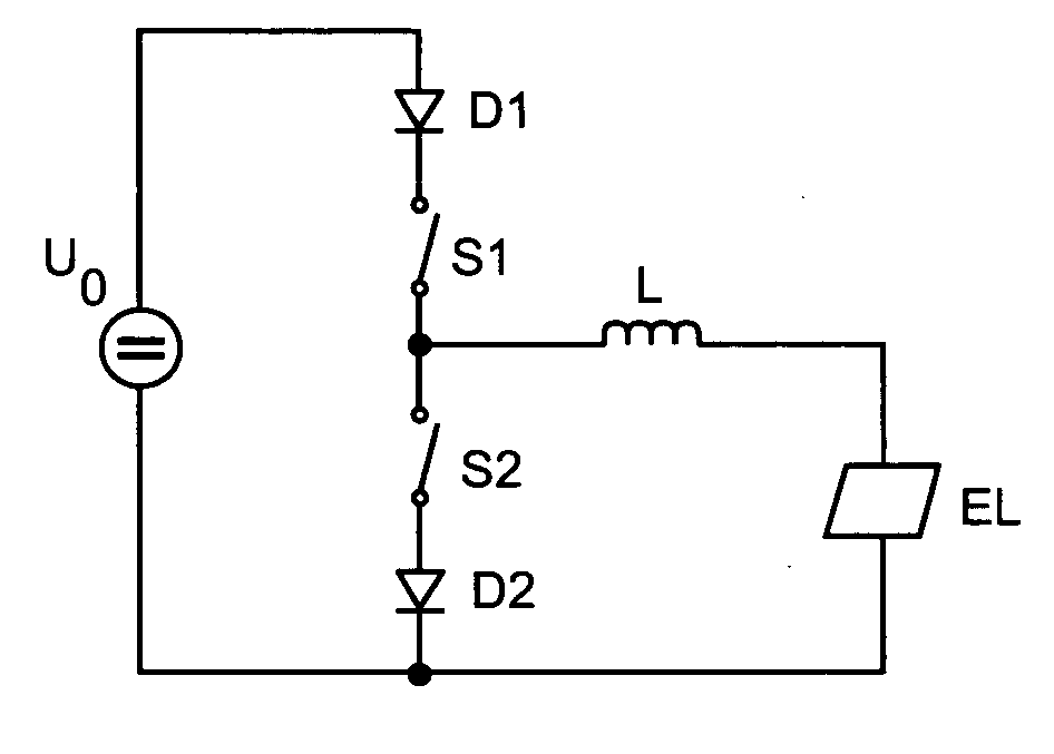
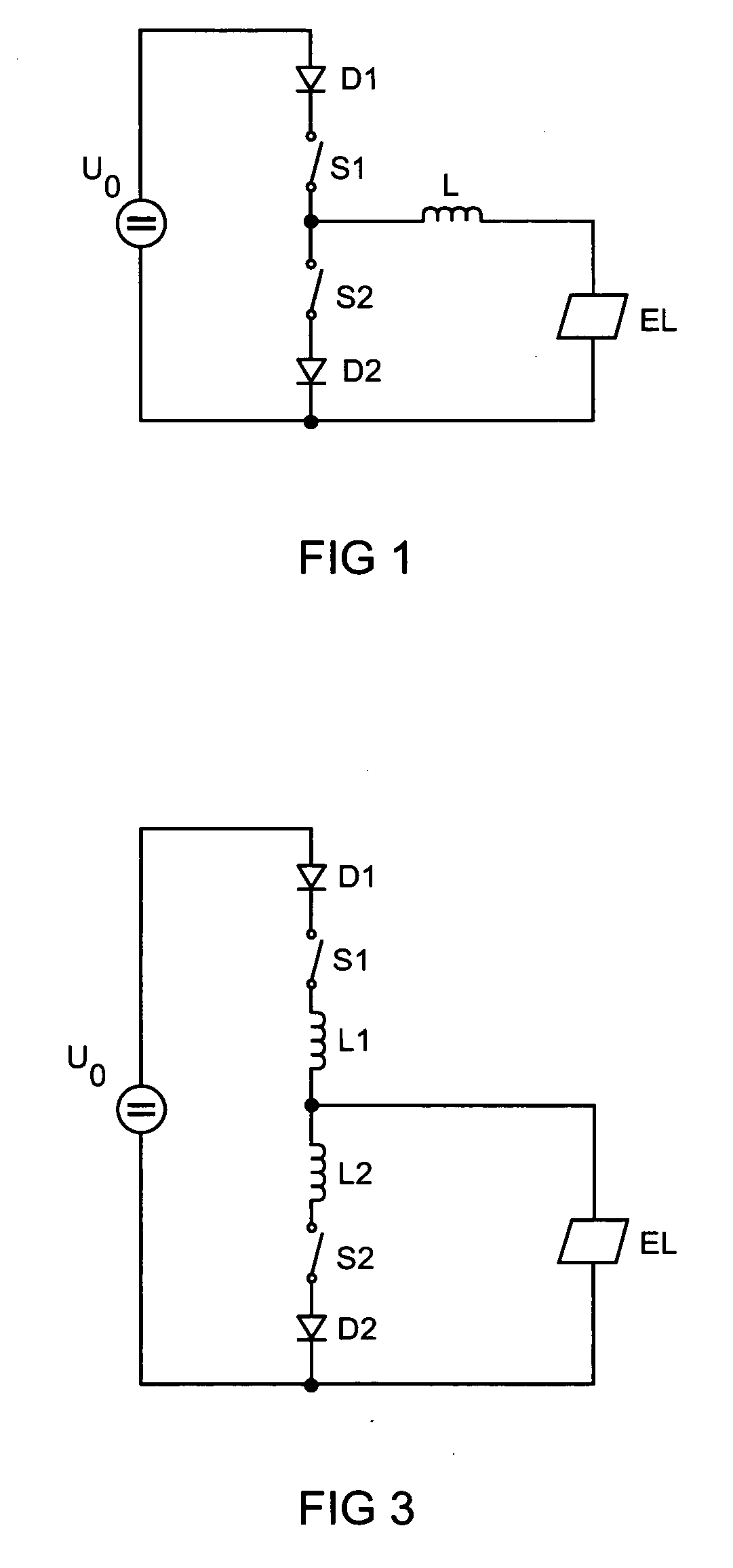
[0032]FIG. 1 shows the basic circuit diagram of a first variant of the half-bridge inductor-type converter according to the invention. Said half-bridge inductor-type converter has two switch branches connected in series which each comprise a current valve D1, D2, for example a diode, and a switch S1, S2, for example a transistor, in particular a field effect transistor (FET) or MOSFET. The center point of the series circuit comprising the two switch branches is connected to a lamp branch, which comprises an inductor L and a dielectric barrier discharge lamp EL connected in series with said inductor L. The lamp branch is connected in parallel with one of the two switch branches. For lamp operation, the terminals of the series circuit comprising the two switch branches are connected to an electrical supply source U0.

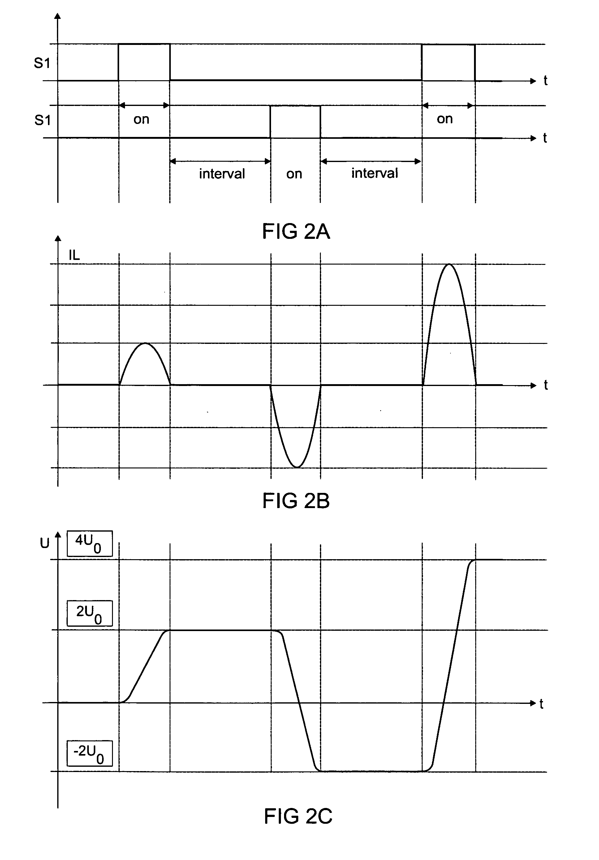
[0033] In order to describe the manner in which the basic circuit shown in FIG. 1 functions, reference will also be made below to the signal profiles illustrated in FIGS....


PUM


Abstract

The circuit arrangement according to the invention comprises an inductor-type converter for the pulsed operation of dielectric barrier discharge lamps (EL). The invention proposes both a half bridge variant and a full bridge variant. By selecting the inductance value of the inductor (L), it is possible to influence the edge steepness of the pulses, in the case of more than one inductor even independently for the rising and falling edges.

Description

TECHNICAL FIELD [0001] The invention relates to a circuit arrangement having a converter without a transformer but with at least one inductor for the pulsed operation of a dielectric barrier discharge lamp. In addition, the invention is aimed at a lighting system having this converter circuit and a dielectric barrier discharge lamp as well as a corresponding operating method. [0002] The term “dielectric barrier discharge lamp” is in this case to be understood as a general term, i.e. it is not merely restricted to lamps emitting in the range of the electromagnetic spectrum which is visible to the human eye. Instead, in this case radiators based on dielectric barrier discharge are also included which, in addition or even predominantly, emit outside this range, in particular also in the ultraviolet range and vacuum ultraviolet range. [0003] From an electrical engineering point of view, dielectric barrier discharge lamps have a predominantly capacitive characteristic owing to the dielec...

Claims


Application Information

Patent Timeline
Patent Type & Authority Applications(United States)
IPC IPC(8): H05B41/16
CPCY02B20/22H05B41/2806Y02B20/00H05B41/30H05B41/26H05B41/14
Inventor KYRBERG, KARLRUPP, ARNULFSCHALLMOSER, OSKAR
Owner PATENT TREUHAND GESELLSCHAFT FUR ELECTRIC GLUEHLAMPEN MBH
Why Eureka
Try Eureka