

Solid electrolytic capacitor
a technology of electrolytic capacitor and solid electrolytic capacitor, which is applied in the direction of liquid electrolytic capacitor, fixed capacitor, fixed capacitor details, etc., can solve the problem that the electrolytic capacitor is not applicable to an application, and achieve the effect of shortening the lead distan
- Summary
- Abstract
- Description
- Claims
- Application Information
AI Technical Summary
Benefits of technology
Problems solved by technology
Method used
Image

Examples
first exemplary embodiment
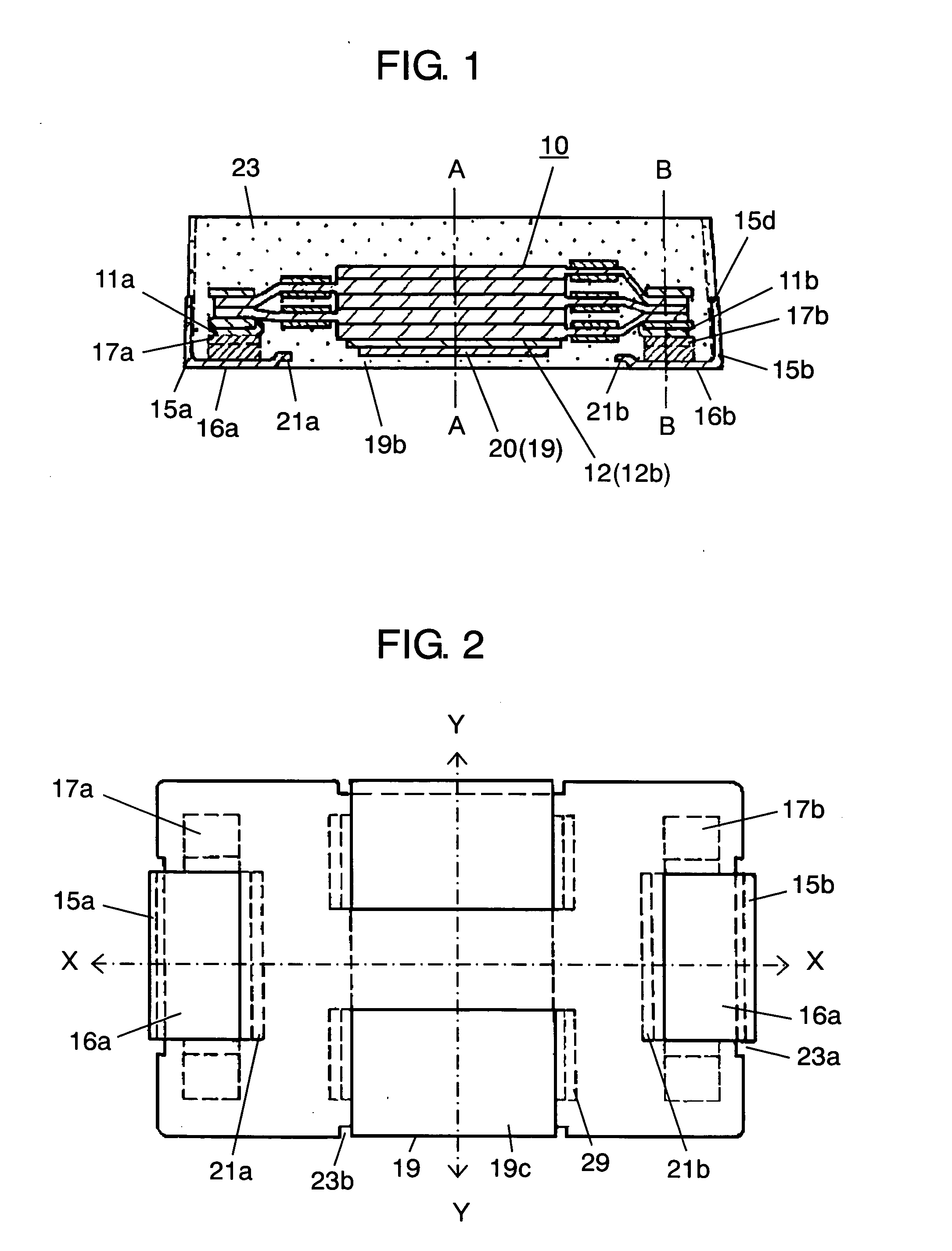
[0043] Hereinafter a description is made for an aspect of the present invention using the first exemplary embodiment.
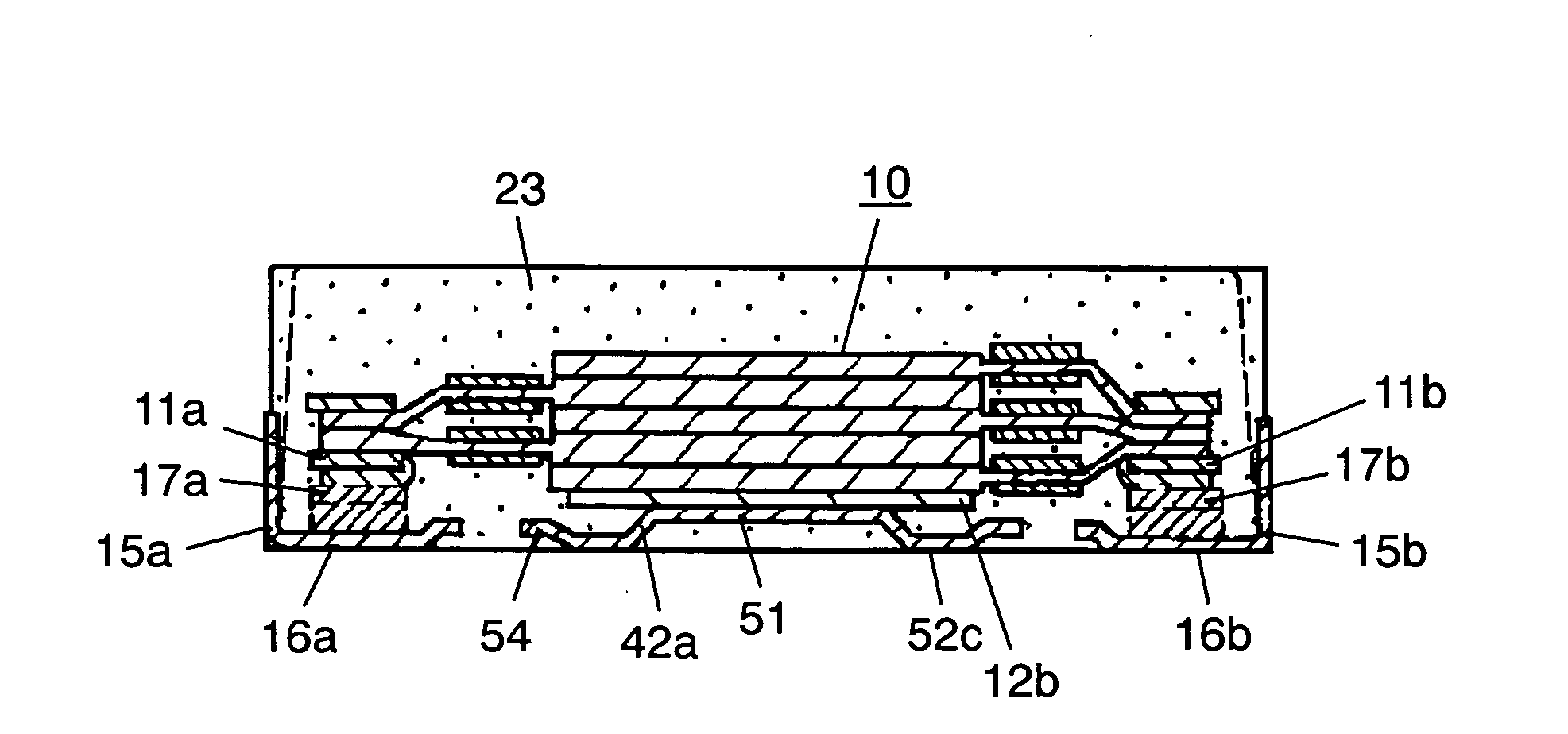
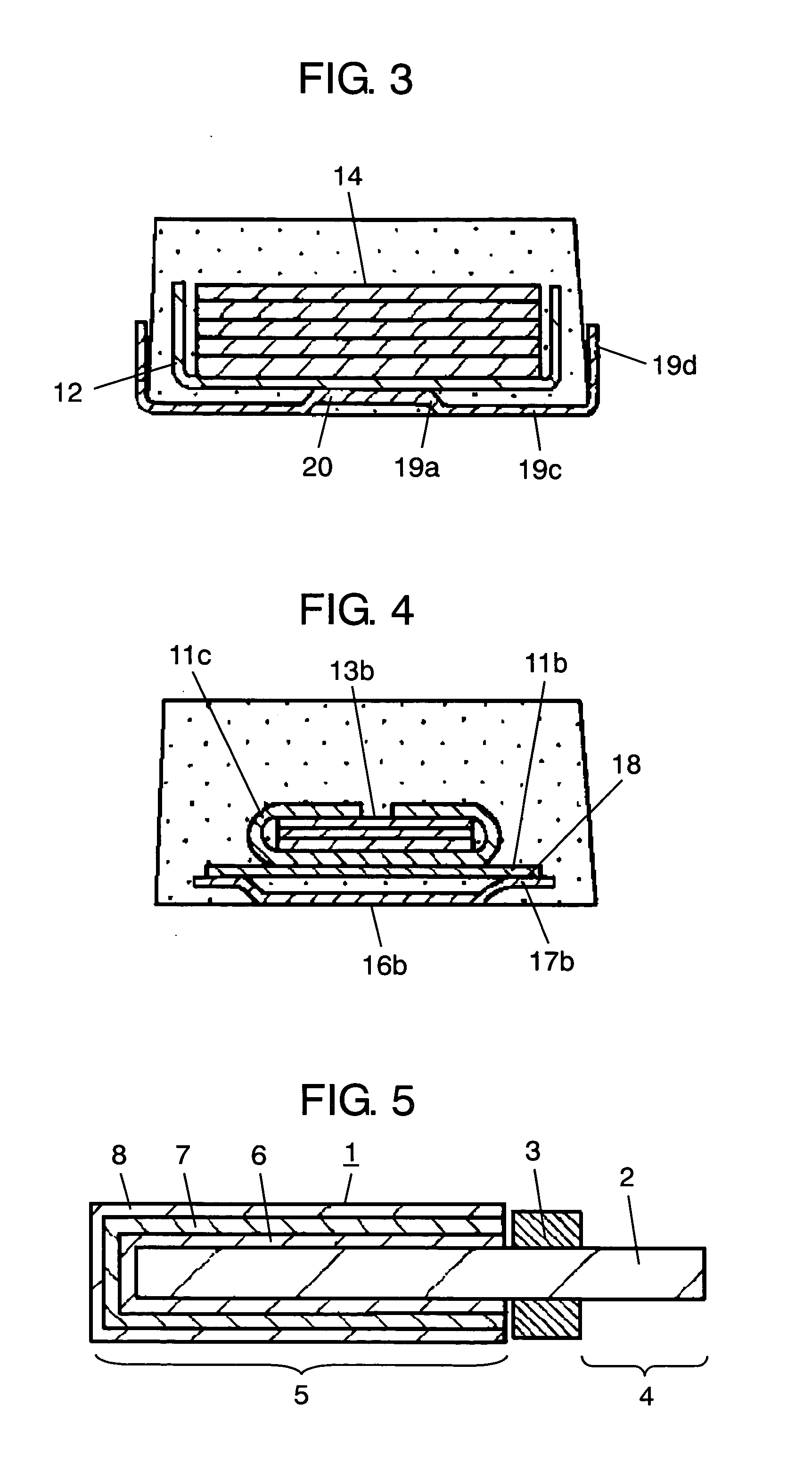
[0044]FIGS. 1 through 4 illustrate the makeup of a solid electrolytic capacitor according to the first exemplary embodiment of the present invention. FIG. 5 is a sectional view illustrating the makeup of a capacitor element used for the solid electrolytic capacitor. FIGS. 6 and 7 illustrate the makeup of the capacitor unit. FIG. 21 is a perspective view of the substantial part illustrating the makeup of an anode terminal and a cathode terminal used for the solid electrolytic capacitor.
[0045] As shown in FIG. 5, capacitor element 1 is sectioned into two components: anode part 4 and cathode part 5, by providing insulator layer 3 on the surface of flat-shaped anode body 2 made of aluminum foil which is a valve metal foil. The surface of anode body 2, extending toward cathode part 5, has thereon dielectric oxide film layer 6, solid electrolyte layer 7 made of conductive...
second exemplary embodiment
[0086] Hereinafter, a description is made for another aspect of the present invention using the second exemplary embodiment.
[0087] The second exemplary embodiment is an embodiment in which the structures of the capacitor element and capacitor unit are partially different from those in the above-mentioned first exemplary embodiment. The makeup other than these are the same as those in the first exemplary embodiment, and thus the same part is given the same mark to omit its detailed description, and a description is made for different parts using related drawings hereinafter.
[0088]FIGS. 8 through 11 illustrate the makeup of a solid electrolytic capacitor according to the second exemplary embodiment of the present invention. FIG. 12 is a sectional view illustrating the makeup of a capacitor element used for the solid electrolytic capacitor. FIGS. 13 and 14 are side view and bottom view illustrating the makeup of the capacitor unit, respectively. FIG. 21 is a perspective view of the s...
third exemplary embodiment
[0118]FIGS. 15 and 16 illustrate the makeup of a solid electrolytic capacitor according to the third exemplary embodiment of the present invention. FIG. 22 is a perspective view of the substantial part illustrating the makeup of an anode terminal and a cathode terminal used for the solid electrolytic capacitor.
[0119] In the third exemplary embodiment, cathode terminal 40 has second flat part 41 that is the entire width of the central part of cathode terminal 40 elevated upward from bottom surface 42c. Second flat part 41 is coupled to bottom 12b of cathode frame 12.
[0120] The part elevated toward this second flat part 41 has a pair of wall surfaces 42a facing the entire width of cathode terminal 40, on the direction connecting between first anode terminal 15a and second anode terminal 15b (the direction of line X-X in FIG. 16, referred to as “lengthwise direction” hereinafter). The pair of wall surfaces 42a mutually face and sandwich second flat part 41. Meanwhile, a pair of openi...
PUM
| Property | Measurement | Unit |
|---|---|---|
| thickness | aaaaa | aaaaa |
| temperature | aaaaa | aaaaa |
| width | aaaaa | aaaaa |
Abstract
Description
Claims
Application Information