Polymeric stent polishing method and apparatus

a technology of polymer stents and polishing methods, applied in auxillary shaping apparatuses, other domestic objects, manufacturing tools, etc., can solve the problem of minimizing residual solvents, and achieve the effect of reducing the stress concentration on the angle of struts

Inactive Publication Date: 2007-02-01
ABBOTT CARDIOVASCULAR
View PDF99 Cites 49 Cited by
  • Summary
  • Abstract
  • Description
  • Claims
  • Application Information

AI Technical Summary

Benefits of technology

[0015] According to a still further aspect of the invention, a method of reducing the stress concentration on angles of struts on a polymeric stent includes: positioning a stent on a spiral-mandrel, the stent including a plurality of struts, the struts having an approximate square cross-section; and after the positioning, applying heat to a surface of the stent from a heat source to smooth out the angles or corners of the struts. The heat can be distributed evenly across the body of the stent or can be specifically directed or concentrated at particular areas of the stent. A concentrated application is preferable when some areas need more polishing than other sections of the stent.

Problems solved by technology

Solvent polishing smoothes out the surfaces and rounds out “sharp corners” of the struts and connecting elements of a polymeric stent; however, adequately removing the solvent and minimizing the residual solvent are problems associated with this method.

Method used


Image

  • Polymeric stent polishing method and apparatus
  • Polymeric stent polishing method and apparatus
  • Polymeric stent polishing method and apparatus

Examples


Embodiment Construction

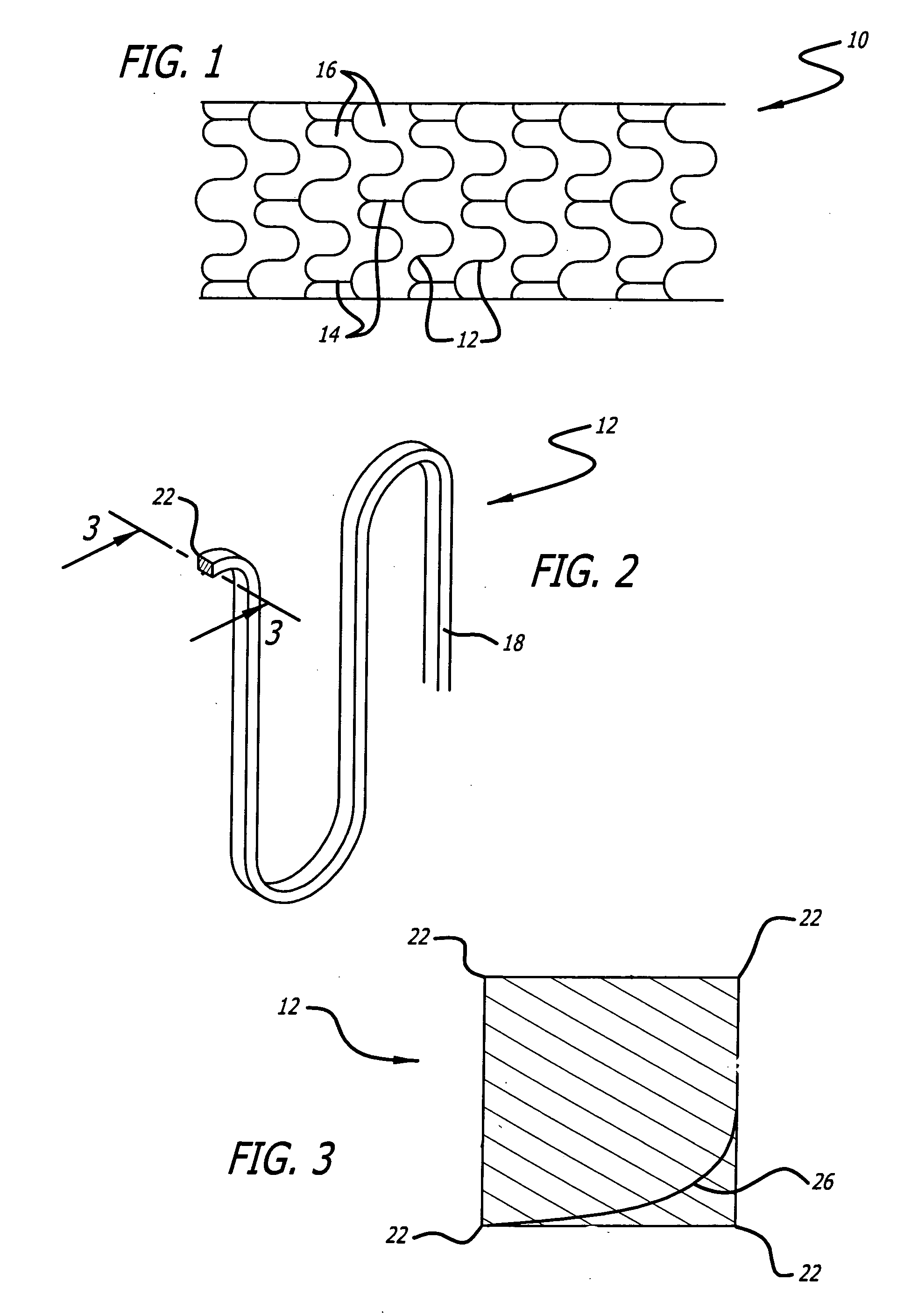
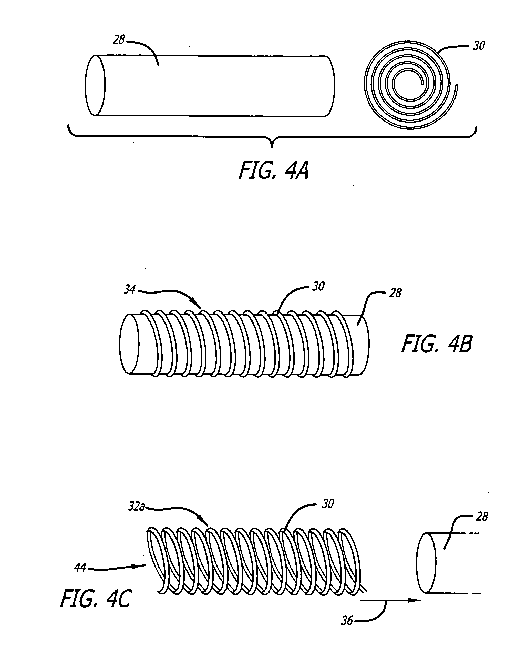
[0046]FIG. 1 illustrates a stent 10, which may be metal or polymeric, preferably polymeric. In either form, the stent 10 can includes a multitude of struts 12 and connecting elements 14, with interstitial spaces 16 located therebetween. Additionally, with respect to a stent constructed from polymer material, the stent 10 may be manufactured by a variety methods, including but not limited to: (a) laser-cutting a flat polymeric sheet in the form of rings and links, and then subsequently rolling the pattern into the shape of the cylindrical stent and providing a longitudinal weld to form the stent; (b) chemically etching a flat polymeric sheet and then subsequently rolling and welding to form the polymeric stent; (c) coiling a polymeric wire to form a polymeric stent, and (d) laser-cutting a pattern of cylindrical rings and connecting rings onto the tube itself. See, e.g., U.S. Pat. No. 6,585,755 to Jackson et al. It has been found, however, that polymeric stents manufactured by conven...


PUM

PropertyMeasurementUnit
temperatureaaaaaaaaaa
lengthaaaaaaaaaa
inner diameteraaaaaaaaaa

Abstract

A method and apparatus for simultaneously polishing the inner and outer surfaces of an unpolished polymeric stent using a heat process. The unpolished stent can be mounted, for example, on a “spiral-mandrel,” a tubular helical structure with gaps in between a series of coils of the structure. Heat from a heat source can then applied to the spiral-mandrel at a range between the glass transition temperature and melting temperature of the polymer of the stent.

Description

BACKGROUND OF THE INVENTION [0001] The present invention relates generally to methods of and apparatuses for polishing radially expandable endoprothesis adapted to be implanted in a lumen of a tubular organ. A “lumen” refers to a cavity of a tubular organ such as a blood vessel. Endoprostheses correspond to artificial implantable medical devices that are placed inside the body, and stents are examples of these endoprostheses. Stents are generally cylindrically shaped devices which function to hold open and sometimes expand a segment of a blood vessel or other anatomical lumens such as urinary tracts and bile ducts. Stents are often used in the treatment of atherosclerotic stenosis in blood vessels. “Stenosis” refers to a narrowing or constriction of the diameter of a body passage or orifice. In such treatments, stents reinforce vessels and prevent restenosis following angioplasty in the vascular system. “Restenosis” refers to the reoccurrence of stenosis in a blood vessel or heart v...

Claims


Application Information

Patent Timeline
Patent Type & Authority Applications(United States)
IPC IPC(8): B29C71/04B29C71/02
CPCA61F2/90A61F2/91B29C59/00B29C71/04B29L2031/7532B29C71/02
Inventor WU, PATRICK P.
Owner ABBOTT CARDIOVASCULAR
Why Eureka
Try Eureka