Switching power supply circuit

a power supply circuit and power supply technology, applied in the direction of power conversion systems, dc-dc conversion, instruments, etc., can solve the problems of high power loss, series regulators and step-down converters inevitably exhibit high power loss, and achieve low power loss by controlling winding

Inactive Publication Date: 2007-02-01
SONY CORP
View PDF5 Cites 37 Cited by
  • Summary
  • Abstract
  • Description
  • Claims
  • Application Information

AI Technical Summary

Benefits of technology

[0081] Meanwhile, each of the remaining secondary side DC output voltages is controlled to a constant voltage by means of the inductance controlled type constant voltage control means. In particular, the inductance controlled type constant voltage control means includes a control transformer as a saturable reactor which includes a controlling winding and a controlled winding, and the controlled winding is inserted in a rectification current path for producing the secondary side DC output voltage of a control object of the control transformer. Then, the level of c...

Problems solved by technology

Further, it is known that the switching converters are limited in enhancement in the power conversion efficiency from their operation characteristics.
However, the power supply circuit described hereinabove with reference to FIG. 14 has the following problems.
In particular, while the circuit shown in FIG. 14 adopts a configuration wherein a series regulator such as the three-terminal regulator 4 and a step-down type converter are added in order to individually stabilize a plurality of secondary side DC output voltages, the series regulator and the step-down type converter inevitably exhibit high power loss.
Therefore, where the load power variation is great as a condition of the load side, the power loss further increases, and consequently, also it becomes necessary to provide a heat radiating plate for the series regulator and/or the step-down type converter, which gives rise to, for example, expansion of the circuit scale and/or increase of the cost.
Where a plurality of switching frequencies are involved in one power supply circuit in this manner, the switching frequencies interfere with each ot...

Method used


Image

  • Switching power supply circuit
  • Switching power supply circuit
  • Switching power supply circuit

Examples


first embodiment

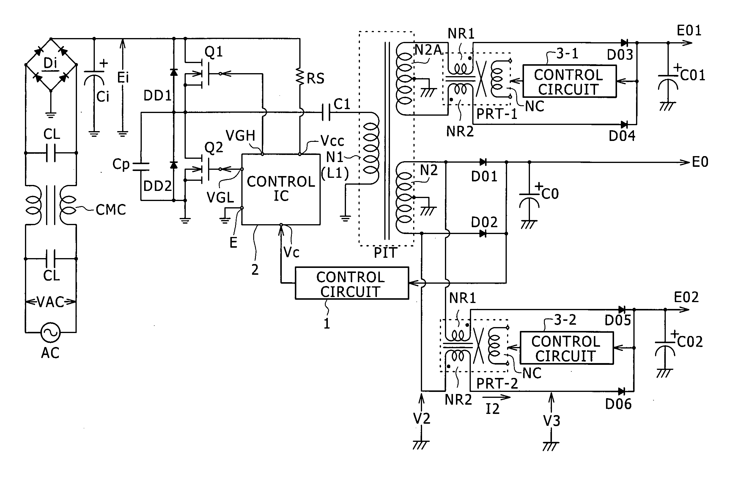
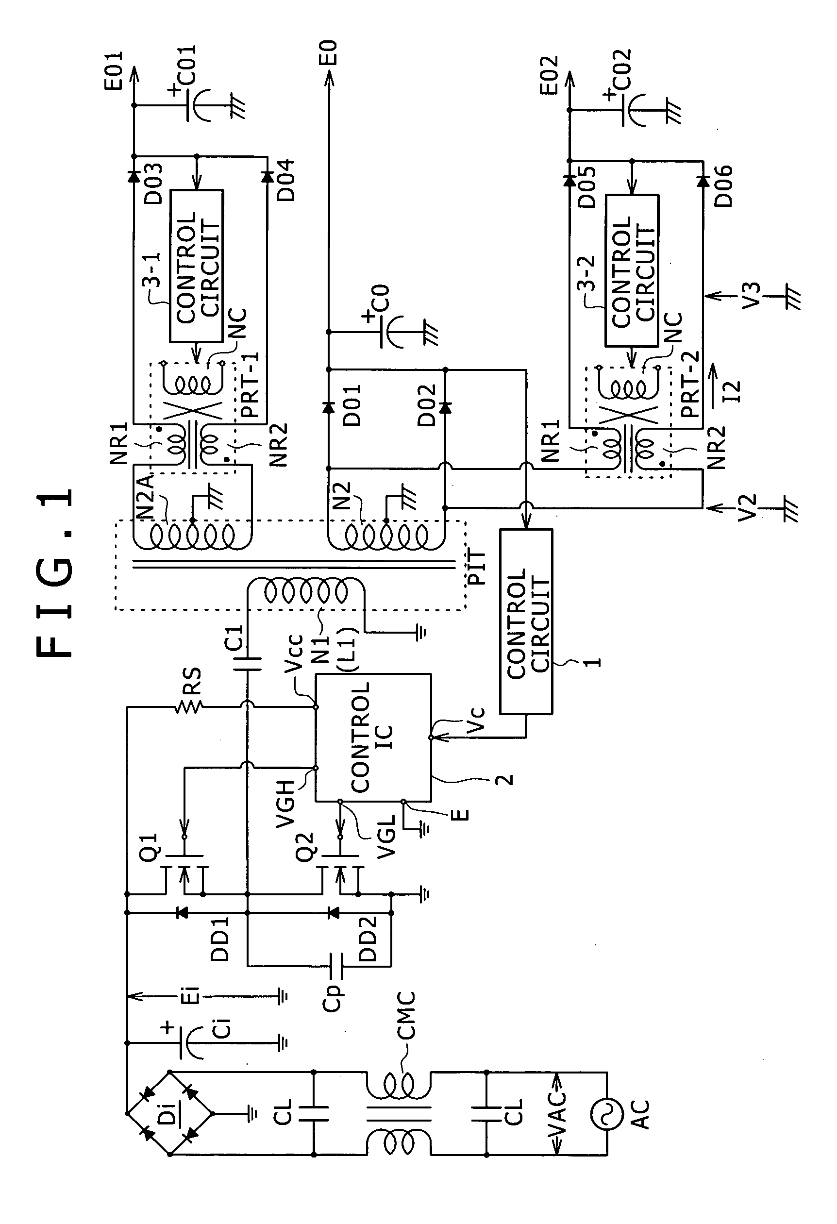
[0102]FIG. 1 shows an example of a configuration of a switching power supply circuit as the present invention.

[0103] In the power supply circuit shown in FIG. 1, a common mode noise filter formed from one common mode choke coil CMC and two across capacitors CL is connected to a commercial AC power supply AC. The common mode noise filter suppresses noise to be transmitted, for example, from the switching converter side to the commercial AC power supply AC.

[0104] Further, a full-wave rectification circuit formed from a bridge rectification circuit Di and a smoothing capacitor Ci is provided in the line of the commercial AC power supply AC at the next stage to the common mode noise filter. A rectification smoothed voltage Ei having a level equal to that of an AC input voltage VAC is obtained as a voltage across the smoothing capacitor Ci by rectification smoothing operation by the full wave rectification circuit.

[0105] A primary side switching converter which receives and operates wi...

second embodiment

[0209]FIG. 10 shows an example of a configuration of a power supply circuit as a It is to be noted that, in FIG. 10, like elements to those of FIG. 1 are denoted by like reference characters and description thereof is omitted herein.

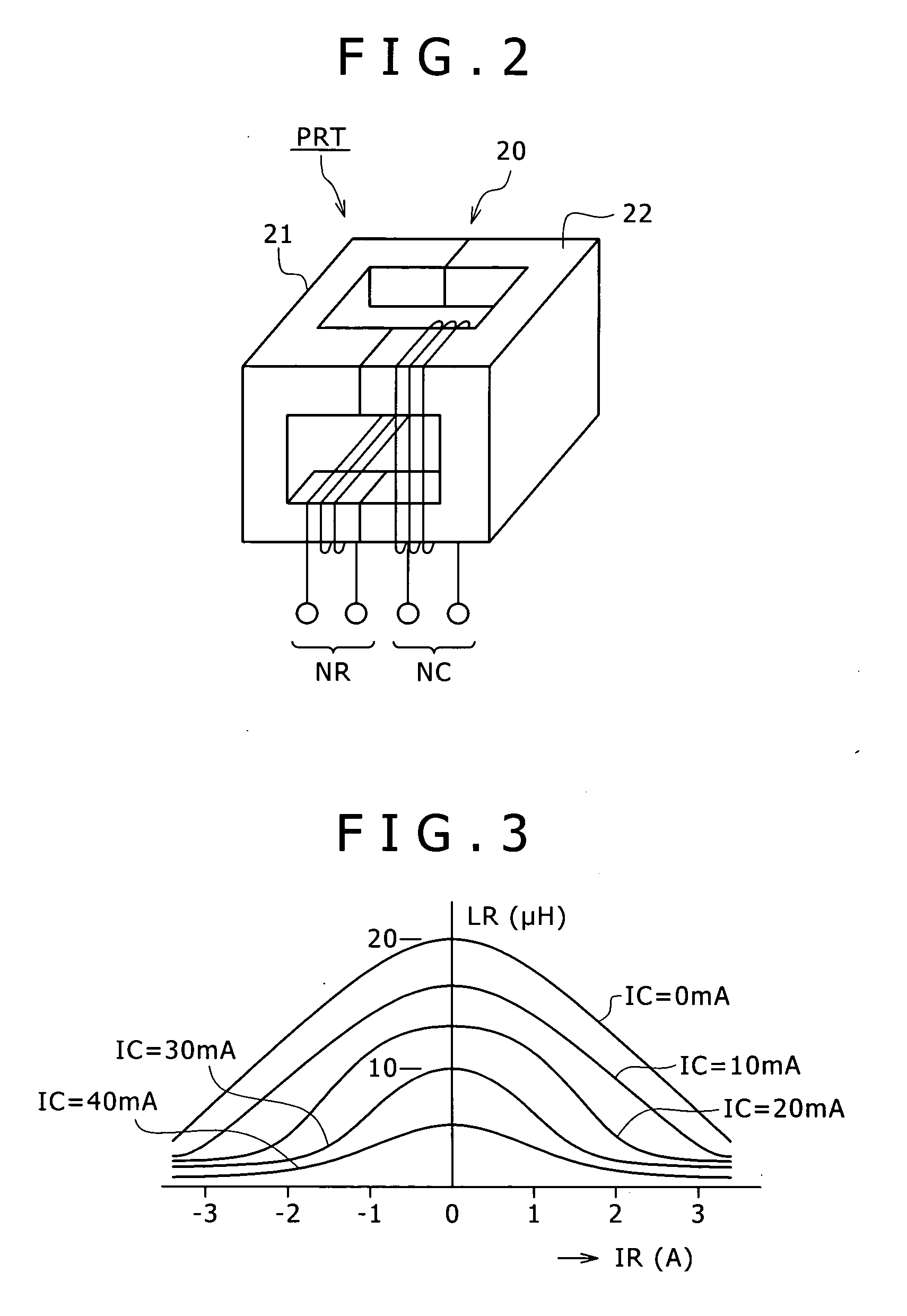
[0210] The orthogonal control transformers PRT (orthogonal control transformers PRT-1 and PRT-2) shown in FIG. 10 may have a configuration similar to that of FIG. 2 described hereinabove.

[0211] In the power supply circuit shown in FIG. 10, the control circuit 3-2 on the secondary side which controls the inductance of the controlled windings NR (NR1, NR2) of the orthogonal control transformer PRT (PRT-1, PRT-2) on the secondary side is configured in such a manner as shown in FIG. 11. It is to be noted that, in FIG. 11, like elements to those of FIG. 4 are denoted by like reference characters and description thereof is omitted herein.

[0212] In the control circuit 3-2 shown in FIG. 11, a capacitor C2 is inserted with the polarities illustrated in FIG. 11...


PUM


Abstract

Enhancement of the power conversion efficiency and reduction of switching noise of a power supply circuit are achieved. The power supply circuit includes, on the primary side, a composite resonance type converter formed from a current resonance type converter and a partial voltage resonance circuit in combination, and is configured so as to produce a plurality of secondary side DC output voltages. A particular one of the plural secondary side DC output voltages is controlled to a constant voltage by variably controlling the switching frequency of a primary side switching converter. Each of the remaining secondary side DC output voltages is controlled to a constant voltage by adjusting the level of control current to be supplied to a controlling winding of a control transformer in response to the level of the secondary side DC output voltage to adjust the inductance of a controlling winding of the control transformer inserted in a rectification current path.

Description

TECHNICAL FIELD [0001] This invention relates to a switching power supply circuit provided as a power supply in various electronic apparatus. BACKGROUND ART [0002] Various switching power supply circuits are widely known including, for example, a switching power supply circuit of the flyback converter type or the forward converter type. The switching converters of the types mentioned are restricted in suppression of switching noise because the switching operation waveform is a rectangular waveform. Further, it is known that the switching converters are limited in enhancement in the power conversion efficiency from their operation characteristics. [0003] Therefore, various switching power supply circuits which rely upon various resonance type converters have been proposed by the applicant of the present application. According to the resonance type converters, a high power conversion efficiency can be obtained readily, and low noise is achieved because the switching operation waveform...

Claims


Application Information

Patent Timeline
IPC IPC(8): H02M3/335G05F1/577H02M3/28H02M3/338
CPCH02M2001/009H02M3/3385H02M1/009H02M3/28
Inventor YASUMURA, MASAYUKI
Owner SONY CORP
Why Eureka
Try Eureka