Fuel cell system and method

Active Publication Date: 2007-02-01
HONDA MOTOR CO LTD
View PDF3 Cites 20 Cited by
  • Summary
  • Abstract
  • Description
  • Claims
  • Application Information

AI Technical Summary

Benefits of technology

[0006] In view of the problem described above, the present invention pro

Problems solved by technology

If a system including the fuel cell is terminated without taking care of the water, the water will freeze under low temperature condition, such as a cold district or a winter season, which invites a problem that performance in terms of low temperature start-up deteriorates.
This leads to a problem that a driver experienc

Method used


Image

  • Fuel cell system and method
  • Fuel cell system and method
  • Fuel cell system and method

Examples


first embodiment

a. First Embodiment

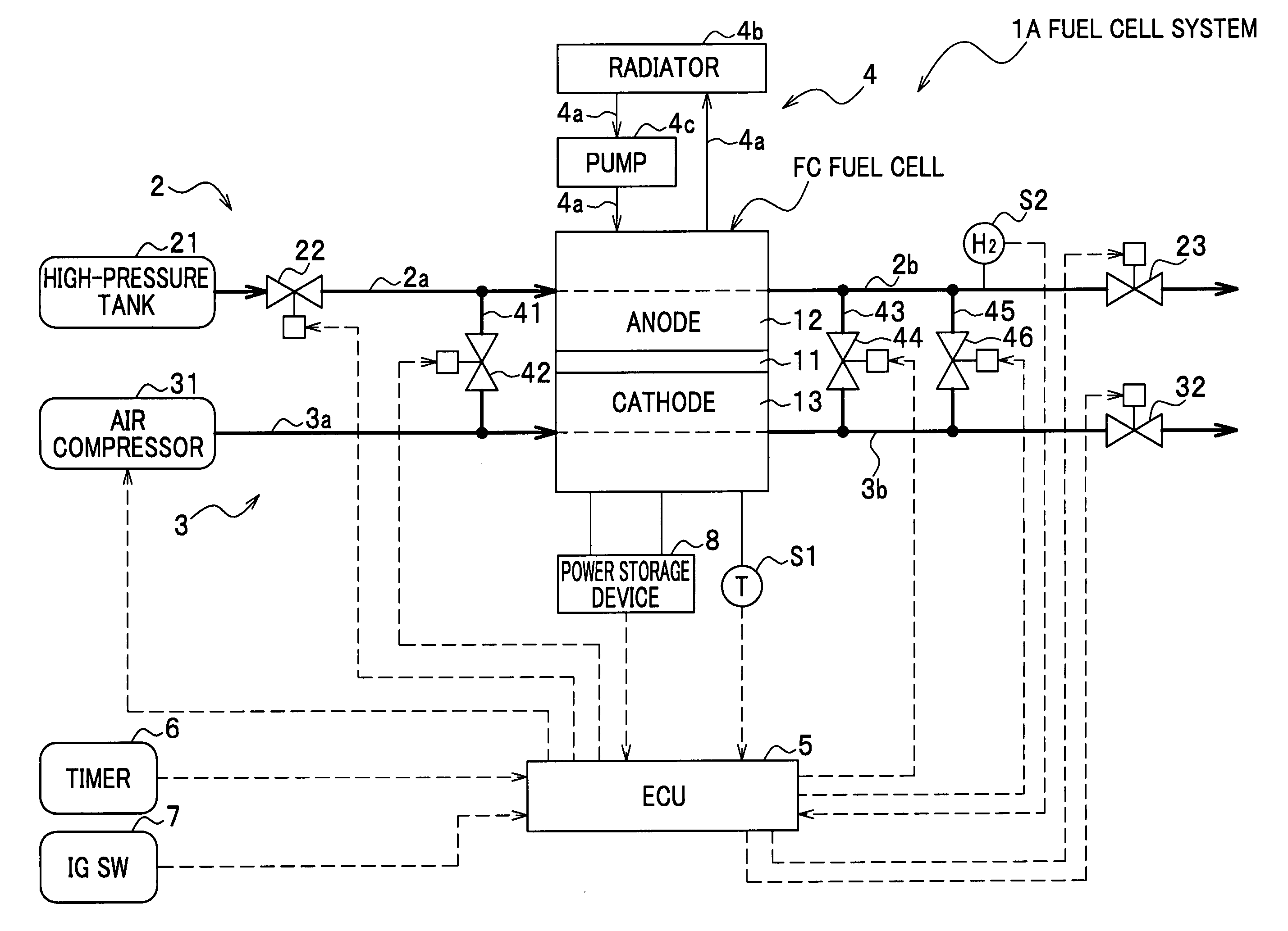
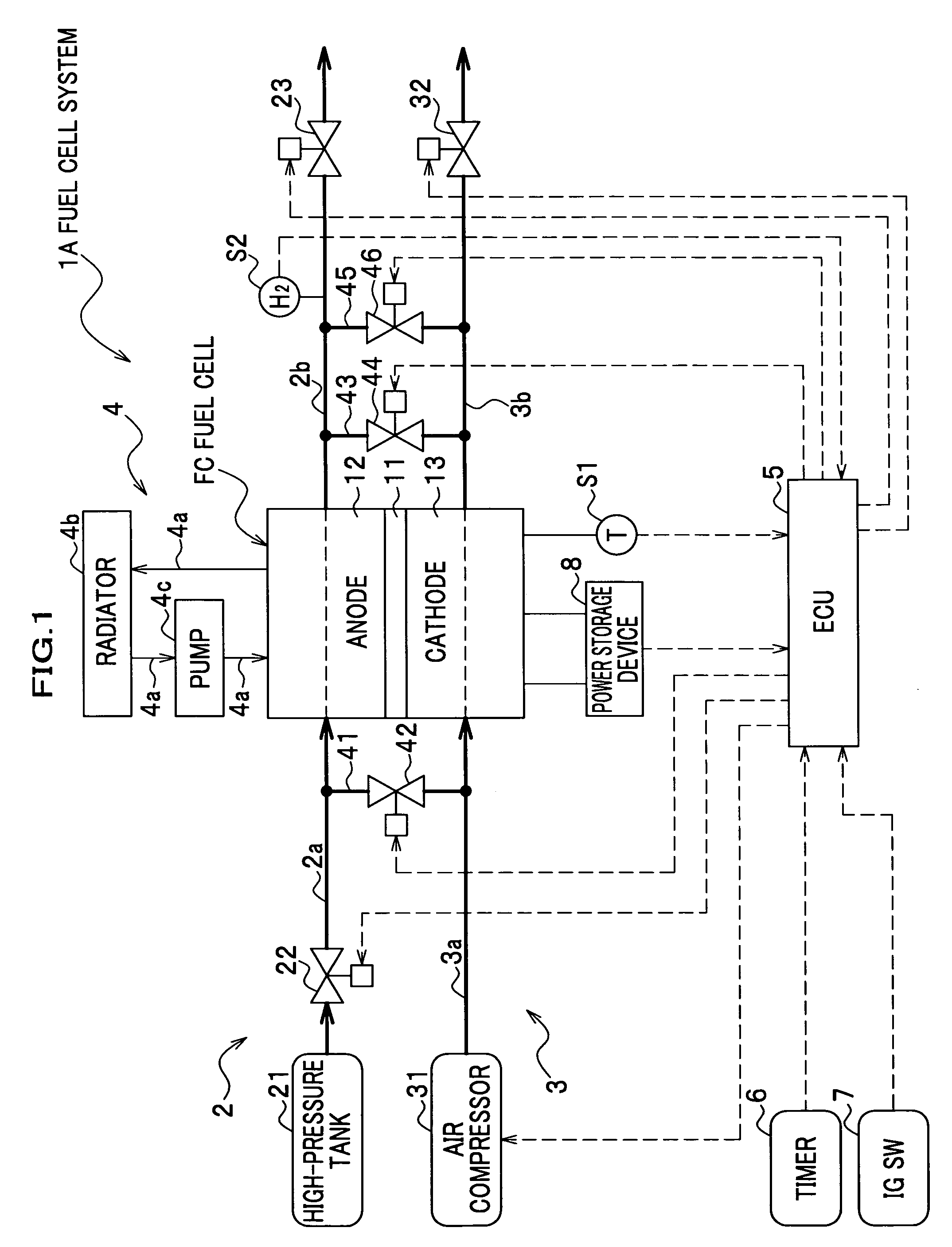
[0024] As shown in FIG. 1, a fuel cell system 1A of a first embodiment of the present invention includes a fuel cell FC, an anode line 2, a cathode line 3, a cooling line 4, an electric control unit (ECU) 5, and the like.

[0025] The fuel cell FC is a Proton Exchange Membrane (PEM) fuel cell of a solid polymer type. The fuel cell FC includes a plurality of stacked cells, each including a Membrane Electrode Assembly (MEA) which is composed of an electrolytic membrane 11 interposed by an anode 12 which includes a predetermined catalyst and a cathode 13. A cell is further interposed by a pair of electrically conductive separators (not shown). When a hydrogen gas and air (oxygen gas) are supplied to the anode 12 and the cathode 13, respectively, hydrogen ions are generated at the anode 12 due to a catalytic action, which migrate to the cathode 13 through the electrolytic membrane 11. Electrons, which are generated in conjunction with the ions at the anode 12, move to t...

second embodiment

b. Second Embodiment

[0057] As shown in FIG. 6, a fuel cell system 1B according to a second embodiment of the present invention includes an additional device, a flowmeter S3, which is disposed in a cathode gas supplying line 3a. As the fuel cell system 1B is structurally similar to that of the first embodiment except for the flowmeter S3, description on other components will not be repeated, bearing the same symbols. The flowmeter S3, which is electrically connected with an ECU 5, detects a flow rate of air supplied by an air compressor 31, sending a signal indicative of the flow rate to the ECU 5.

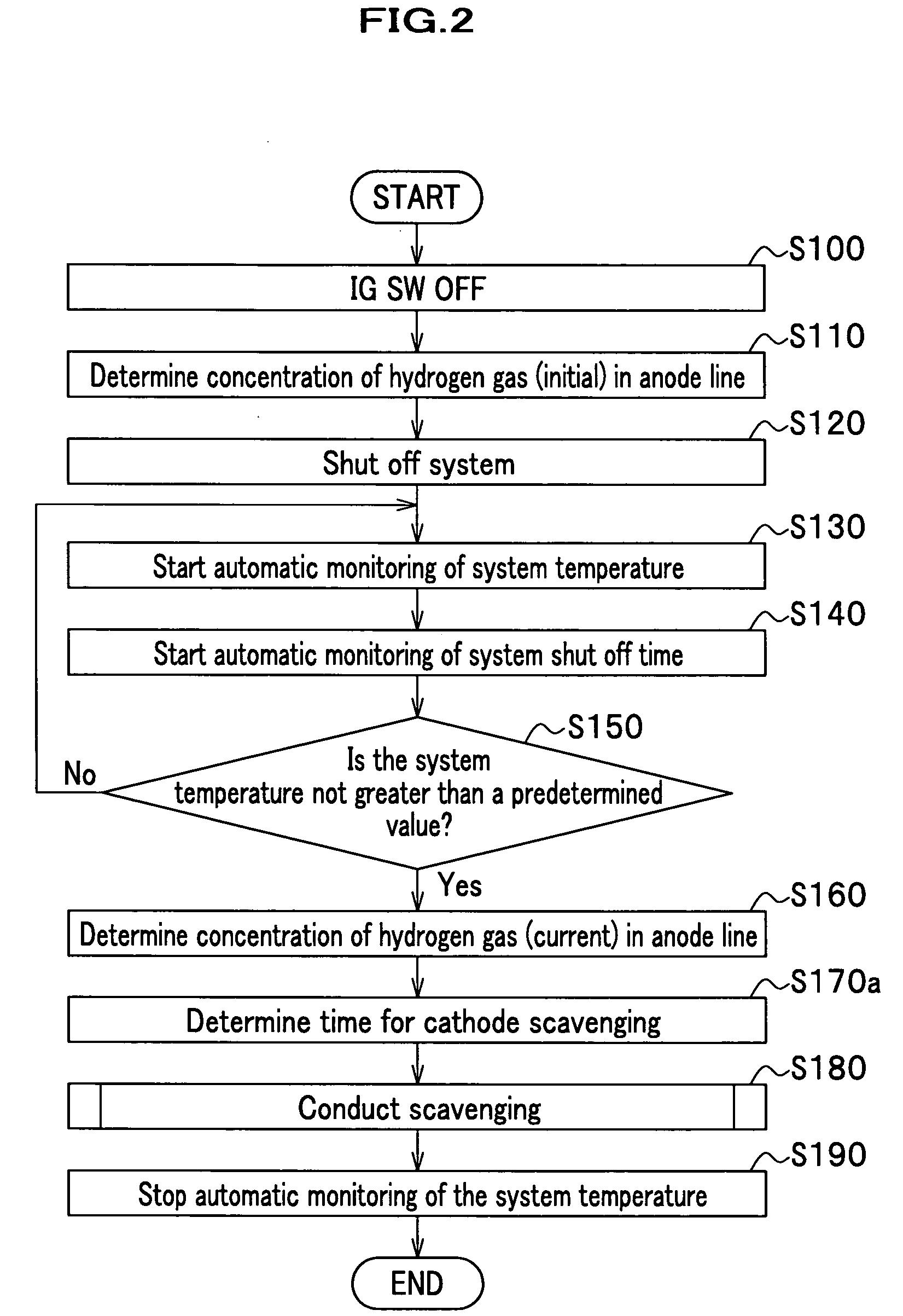
[0058] Description is given of scavenging process conducted by the fuel cell system 1B according to the second embodiment with reference to FIGS. 7 to 10. It should be noted that a flow shown in FIG. 7 is similar to that in FIG. 2 of the first embodiment except for a step S170b replacing a step S170a. Also, a flow shown in FIG. 9 is similar to that in FIG. 4 except for a step S183b replaci...


PUM


Abstract

A fuel cell system and a method for scavenging it are provided. The fuel cell system includes a fuel cell, a fuel gas passage, an oxidant gas passage, a communicating passage, a communicating valve, a monitoring device, a valve controller, a scavenging device and a computing device. The monitoring device monitors a state transition of the fuel cell after a termination of power generation. The valve controller opens the communicating valve when a signal indicative of the state transition meets a predetermined criterion. The scavenging device includes a first scavenging device for the oxidant gas passage, and a second scavenging device for the fuel gas passage. The computing device computes an amount of the oxidant gas required for scavenging according to a system shut off time. The scavenging device conducts scavenging with the amount of the oxidant gas obtained by the computing device.

Description

BACKGROUND OF THE INVENTION [0001] The present invention relates to a fuel cell system, which can be started up under low temperature condition and a method for scavenging the fuel cell system. [0002] As an example of a fuel cell mounted on an electric vehicle, a fuel cell categorized as a type of Proton Exchange Membrane (PEM) has been generally known, which employs solid polymers as electrolytic membranes. The fuel cell of this type has stacked layers of cells, each of which has an anode and a cathode interposing an electrolytic membrane. When a hydrogen gas and air (oxygen gas) are supplied to the anode and cathode, respectively, they cause an electrochemical reaction, generating power and water. [0003] It is known that when power generation by a fuel cell is terminated, water remains in lines and the fuel cell. If a system including the fuel cell is terminated without taking care of the water, the water will freeze under low temperature condition, such as a cold district or a wi...

Claims


Application Information

Patent Timeline
IPC IPC(8): H01M8/04H01M8/12
CPCH01M8/04007H01M8/04223H01M8/04328H01M8/04335H01M8/04343H01M8/0435Y02E60/50H01M8/04462H01M8/04567H01M8/04753H01M8/04761H01M8/04783H01M2008/1095H01M8/04395H01M8/241H01M8/2457H01M8/04302
Inventor OGAWA, JUMPEIWAKE, CHIHIROMIYATA, KOICHIRO
Owner HONDA MOTOR CO LTD
Why Eureka
Try Eureka