Inter-domain congestion charging

a congestion charging and inter-domain technology, applied in the field of network operation methods, can solve problems such as inpracticability, and achieve the effects of convenient scalability of ecn charging, convenient operation of congestion charging schemes, and convenient operation

Active Publication Date: 2007-02-01
BRITISH TELECOMM PLC +1
View PDF6 Cites 28 Cited by
  • Summary
  • Abstract
  • Description
  • Claims
  • Application Information

AI Technical Summary

Benefits of technology

[0013] The invention of the first aspect therefore facilitates scalable inter-domain congestion charging by simply counting the number of packets which have the CE code-point set within the ECN bits which are passed to each data receiving entity, irrespective of the individual data flow to which each packet belongs, and generating the congestion charge signal in dependence on the count. Moreover, the data receiving entities may be an ingress router of a subsequent network domain or an actual end-user receiver connected via an ISP domain, and the operation of the invention within each such network domain through which data packets pass between the transmitter and the receiver allows the congestion charges accumulated by the data packets along the route to ripple along the network from the transmitter's ISP domain through each subsequent network domain and then ultimately to be passed onwards to the receiver.
[0015] By applying a tariff function then the final congestion charge signal generated may take into account external factors, such as time of day, or the like. In such embodiments it is further possible for different tariff functions to be applied to at least some of the respective counts such that different congestion charges are levied pro rata on at least some of the data packet receiving entities. This further increases the charging structure flexibility within the same technological framework of the invention.
[0016] Within the preferred embodiments, the further steps of receiving data packets from one or more data transmitting entities, at least some of the received data packets containing control data indicating that the packet has experienced congestion; and receiving respective congestion charge signals from the or each data transmitting entities indicating the respective congestion charges to be levied for receiving the received data packets therefrom are performed. This feature allows the charges to ripple towards the receiver, thus providing ready scalability of ECN charging.
[0017] In the preferred embodiments, the counting step is preferably performed for the or each data receiving entity over a respective aggregation period, and the generating step further acts to generate the respective congestion charge signal for a particular data receiving entity once per aggregation period. This allows for aggregate charging irrespective of individual data flows to be performed, which further simplifies the congestion charging scheme.
[0026] The methods of the second and third aspects provide the same advantages as previously described in respect of the first aspect, but with the additional advantage that the billing server can be operated separately from the network. In some implementations this may provide for economies of scale, as a single billing server may service each network domain's egress routers.

Problems solved by technology

Such an approach indicates a “per flow” charging policy, however, which may not be practicable, and especially between different network domains which a flow may encounter between the sender and receiver, due to the potentially high number of individual flows which might pass between two network domains.
Additionally, there is an added problem using ECN marks to generate the shadow price that it is not until the packets of a flow have arrived at the receiver that the number of packets in the flow with the CE code-point set can be properly measured, as at any point on the route before this further packets may have the CE code-point set at any router later in the route.
There is therefore a further problem of generating the level of shadow charges for use on an inter-domain basis between network domains without having knowledge of the total shadow charge which will ultimately arise.

Method used


Image

  • Inter-domain congestion charging
  • Inter-domain congestion charging
  • Inter-domain congestion charging

Examples


Embodiment Construction

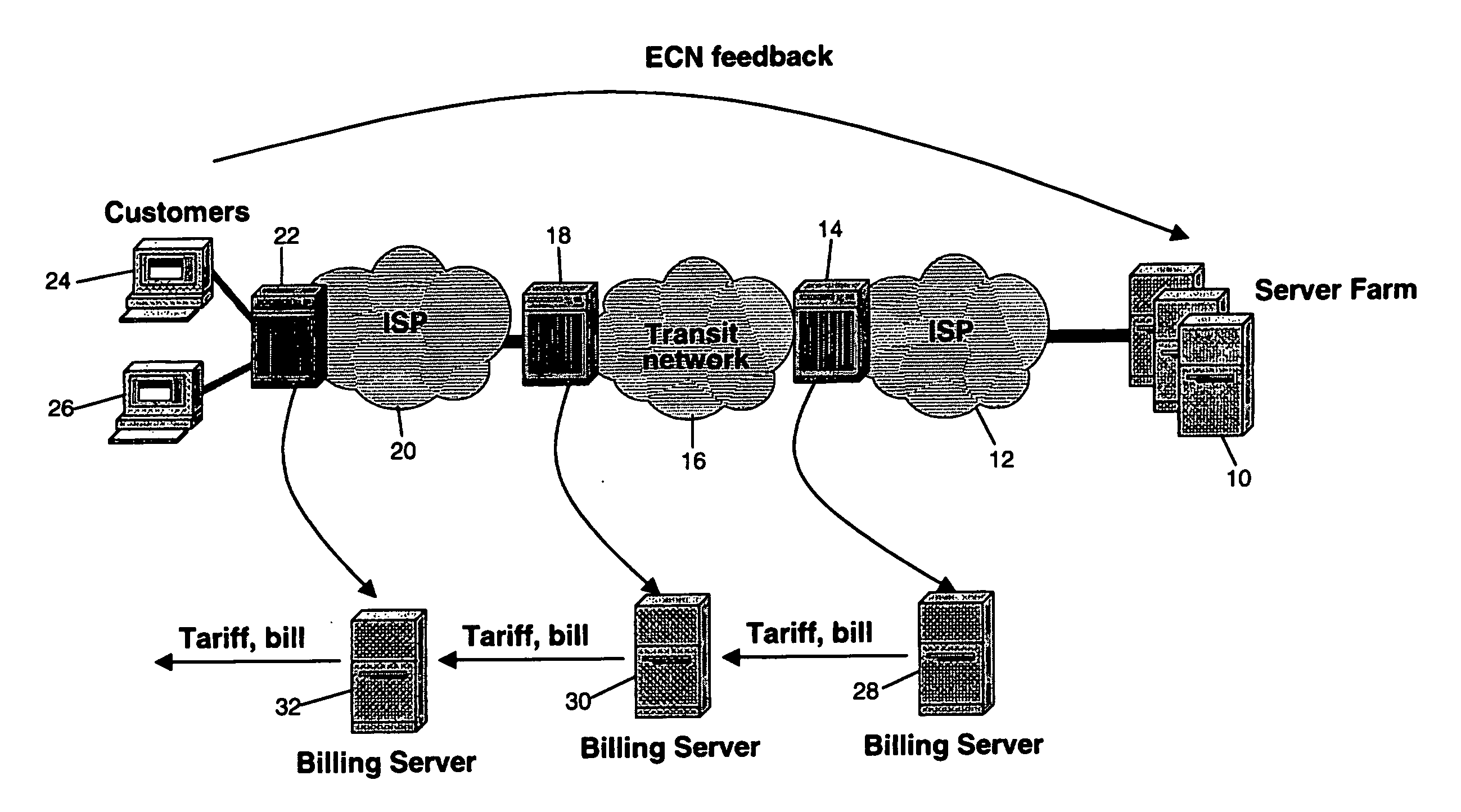
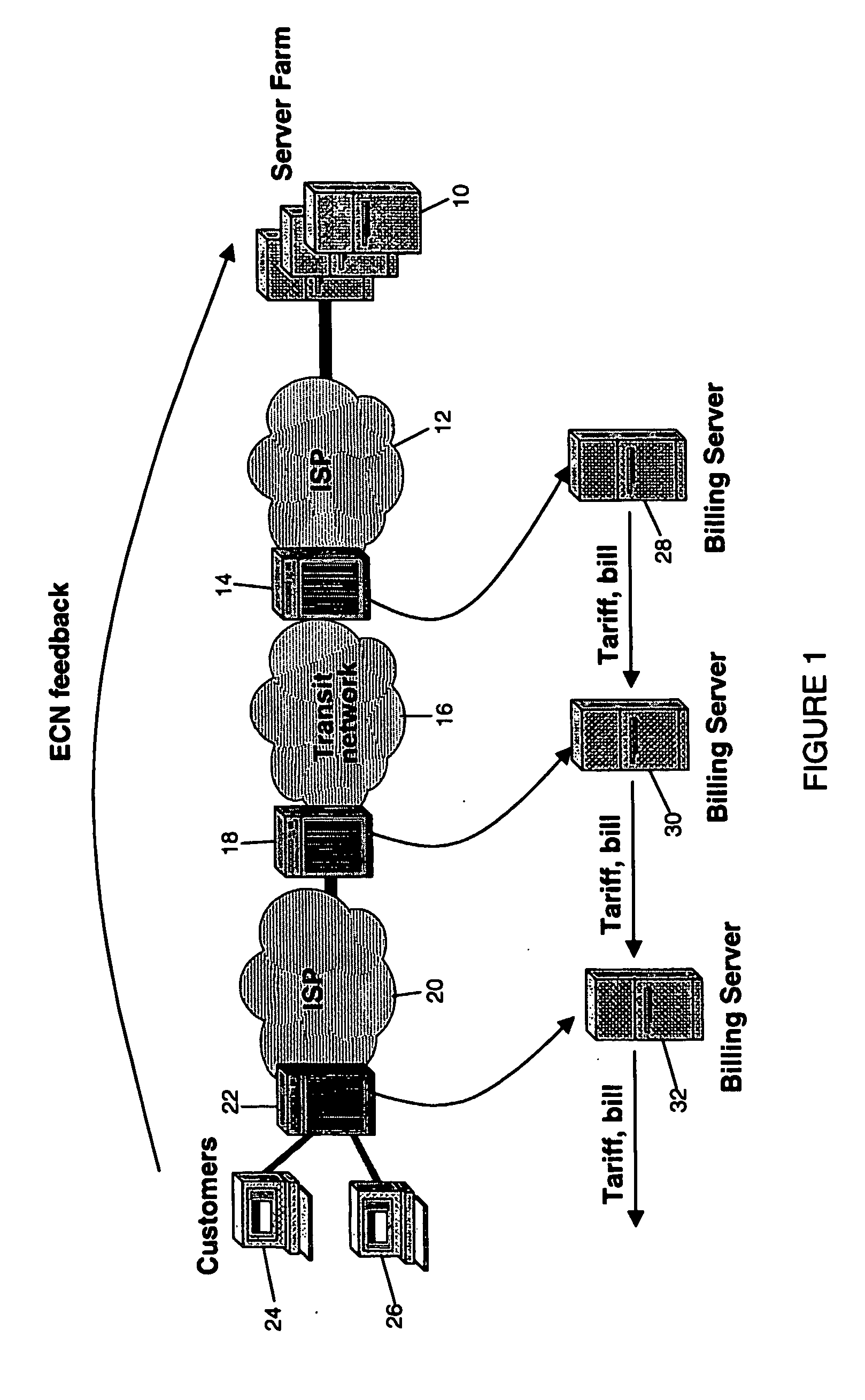
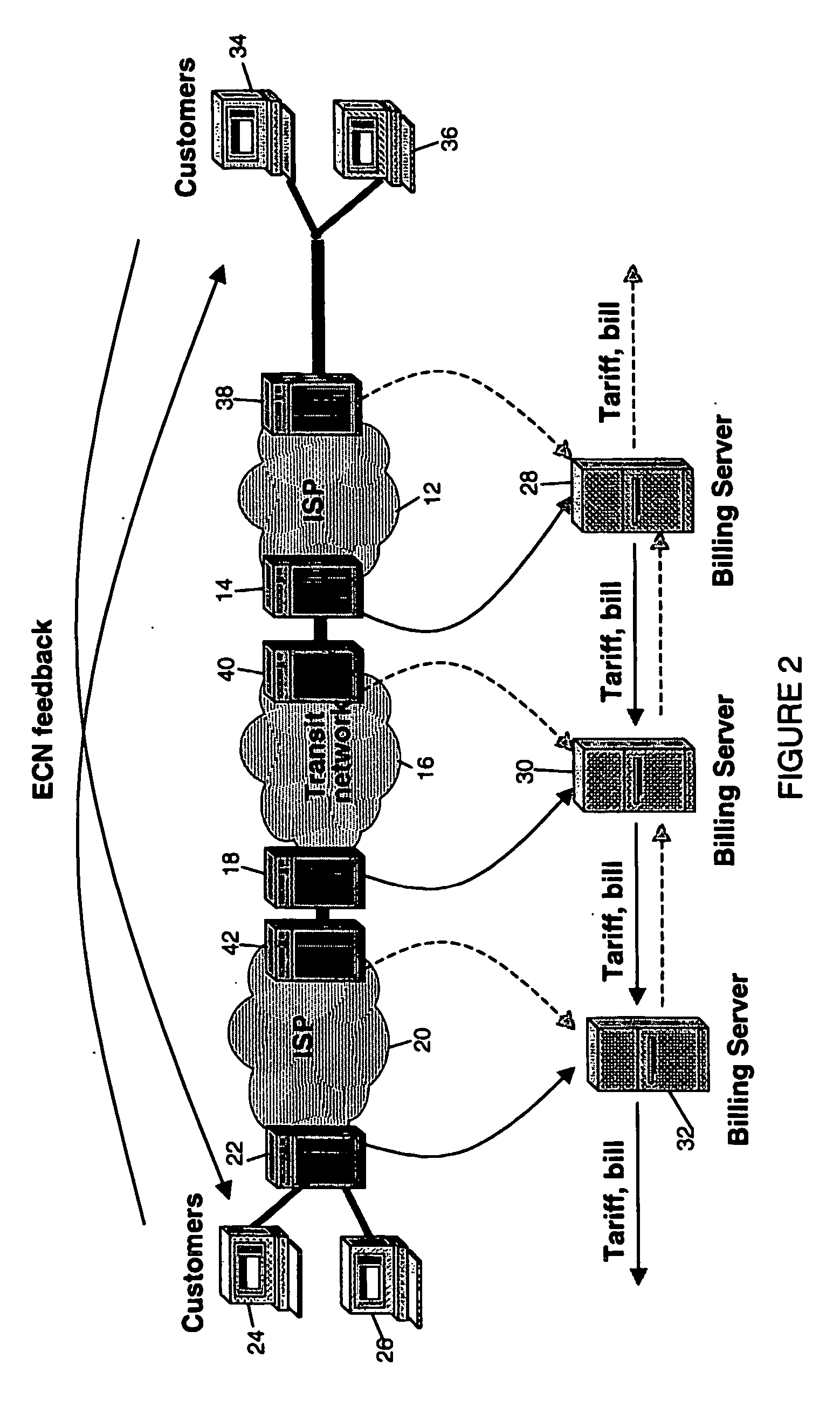
[0053]FIGS. 1 and 2 are stylised diagrams which provide an overview of the operation of the embodiments of the invention. FIG. 2 differs from FIG. 1 in that it illustrates the situation where traffic is being sent in both directions over the various networks, whereas FIG. 1 illustrates the simpler situation where traffic is being sent in one direction.

[0054] With reference to FIG. 1, the operating environment of the embodiments of the invention where traffic is being sent in a single direction comprises a server farm 10 which constitutes the source of the traffic, a first ISP network domain 12 provided with an egress route 14, a transit network domain 16 connected to the egress router 14 of the first ISP network domain 12, and a second egress router 18 provided as part of the transit network 16. A second ISP network domain 20 is connected by the egress router 18 of the transit network 16, and is further provided with its own egress router 22 which connects the second ISP network do...


PUM


Abstract

A method and system to allow congestion charging signals to be generated and congestion charges to be applied on an inter-domain basis, on an aggregated basis and not on a per flow basis. Each network domain charges its neighbouring domain for any ECN marks that it forwards to them. Since a flow will collect marks as it progresses across the network the last network domain (typically an Internet service provider (ISP) located at the edge of the network domains) will levy a charge based on a higher number of marks than any of the charges levied by other domains involved in the transmission of the flow, and this higher charge can be passed on to the end user, preferably as a single aggregated charge per subscriber per accounting period. Each network domain (whether an edge ISP or other domain such as an intermediate ISP) will forward traffic to other network domains and consequently can produce a single aggregated charge per connected domain.

Description

TECHNICAL FIELD [0001] The present invention relates to a method of operating a network to permit inter-domain congestion charging, and to related apparatus arranged to perform the method. BACKGROUND TO THE INVENTION AND PRIOR ART [0002] Explicit Congestion Notification (ECN) has been proposed for use within Internet Protocol (IP) networks, and involves ECN capable routers marking packets as having experienced congestion by the use of specific ECN fields within the packet header, rather than dropping the packet and leaving the receiver to infer congestion, as had previously been the case (as packet loss could also be caused by transmission errors, loss of a packet is no definitive indicator of network congestion). Within IP, a two-bit field within the IP header has been proposed to enable the marking of packets, comprising a first ‘ECN-Capable Transport’ (ECT) bit (which was generally intended to be used to indicate whether the end-points of the transport protocol were ECN capable) ...

Claims


Application Information

Patent Timeline
Patent Type & Authority Applications(United States)
IPC IPC(8): G06F15/173H04L12/14H04L12/24H04L12/801
CPCH04L12/14H04L12/1446H04L12/1489H04L12/24H04L41/00H04M2215/7428H04L47/12H04L47/35H04M15/8027H04M2215/22H04L47/10
Inventor RUDKIN, STEVEN
Owner BRITISH TELECOMM PLC
Why Eureka
Try Eureka