Powertrain battery life predicting and warning apparatuses

a technology for warning apparatuses and powertrains, which is applied in the direction of engines, instruments, transportation and packaging, etc., can solve the problems of promoting battery deterioration, deteriorating battery life, and deteriorating battery installed as a power source in a powertrain

Active Publication Date: 2007-02-08
TOYOTA JIDOSHA KK
View PDF3 Cites 88 Cited by
  • Summary
  • Abstract
  • Description
  • Claims
  • Application Information

AI Technical Summary

Benefits of technology

[0022] The present invention advantageously provides an apparatus for predicting remaining life of a battery and an

Problems solved by technology

Specifically, at the time of starting the vehicle or during light load running with poor engine efficiency, for example, the vehicle is mainly powered by the electric motor while making full use of the battery.
A battery installed as a power source in a powertrain deteriorates with time through normal usage, and the life of the battery expires at some point in time because the capability of charging/discharging a cell (a battery capacity) gradually drops as internal resistance of the battery increases due to prolonged running.
Overcharging or over discharging of the battery promotes battery deterioration.
Because increases of the running distance generally leads to increased battery deterioration, the running distance is regarded as a factor influencing battery deterioration.
Because, in the running test of an actual vehicle, the entire vehicle is subjected to the test, the factors having an effect on performance of the power output device are great in number and in complexity, which causes a problem in accuracy of evaluated data.
On the other hand, in the method for removing only the power output device and evaluating the power output device on the test bench, the accessory devices, such as an air conditioner, mounted on the vehicle are not equipped to the test bench, which causes a problem in that effects exerted by the accessory devices remain undetected and constitute an error of the test.
Because an error contained in an estimation based on only a specific one of

Method used


Image

  • Powertrain battery life predicting and warning apparatuses
  • Powertrain battery life predicting and warning apparatuses
  • Powertrain battery life predicting and warning apparatuses

Examples


Embodiment Construction

[0047] Referring to the drawings, an embodiment of the present invention will be described below.

(1) Powertrain Battery Life Predicting Apparatus

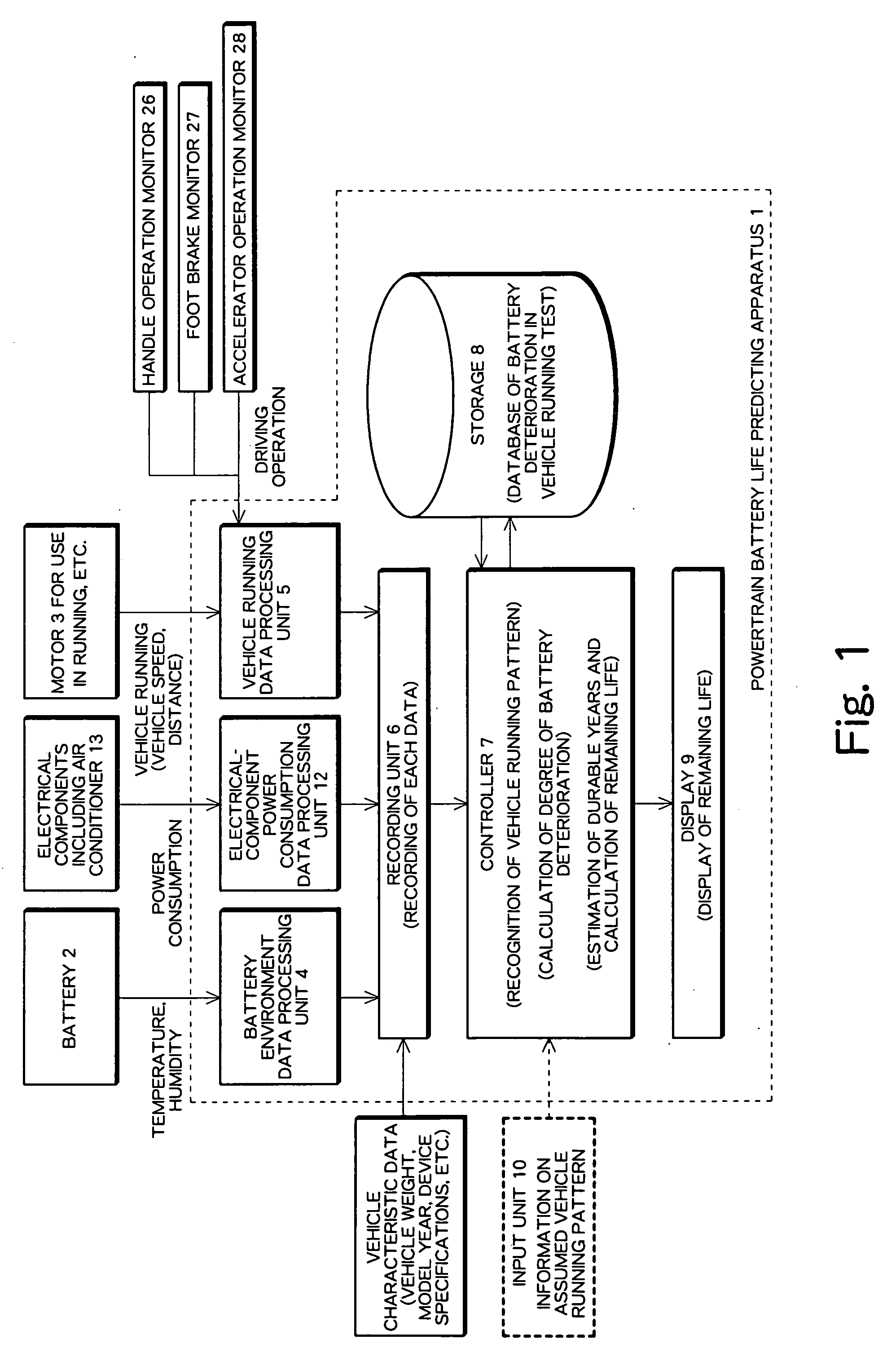
[0048]FIG. 1 schematically shows a basic configuration of a powertrain battery life predicting apparatus 1 according to an embodiment of the present invention. This apparatus comprises an environment data processing unit 4 for processing data on environment around a battery 2, a power consumption data processing unit 12 for processing power consumption data concerning electrical components, a vehicle running data processing unit 5, a recording unit 6, a controller 7, a storage 8, and a display 9.

[0049] Here, the term “battery” refers to a high-voltage battery of 144V˜288V for supplying power to an inverter which drives and controls a motor used for vehicle running.

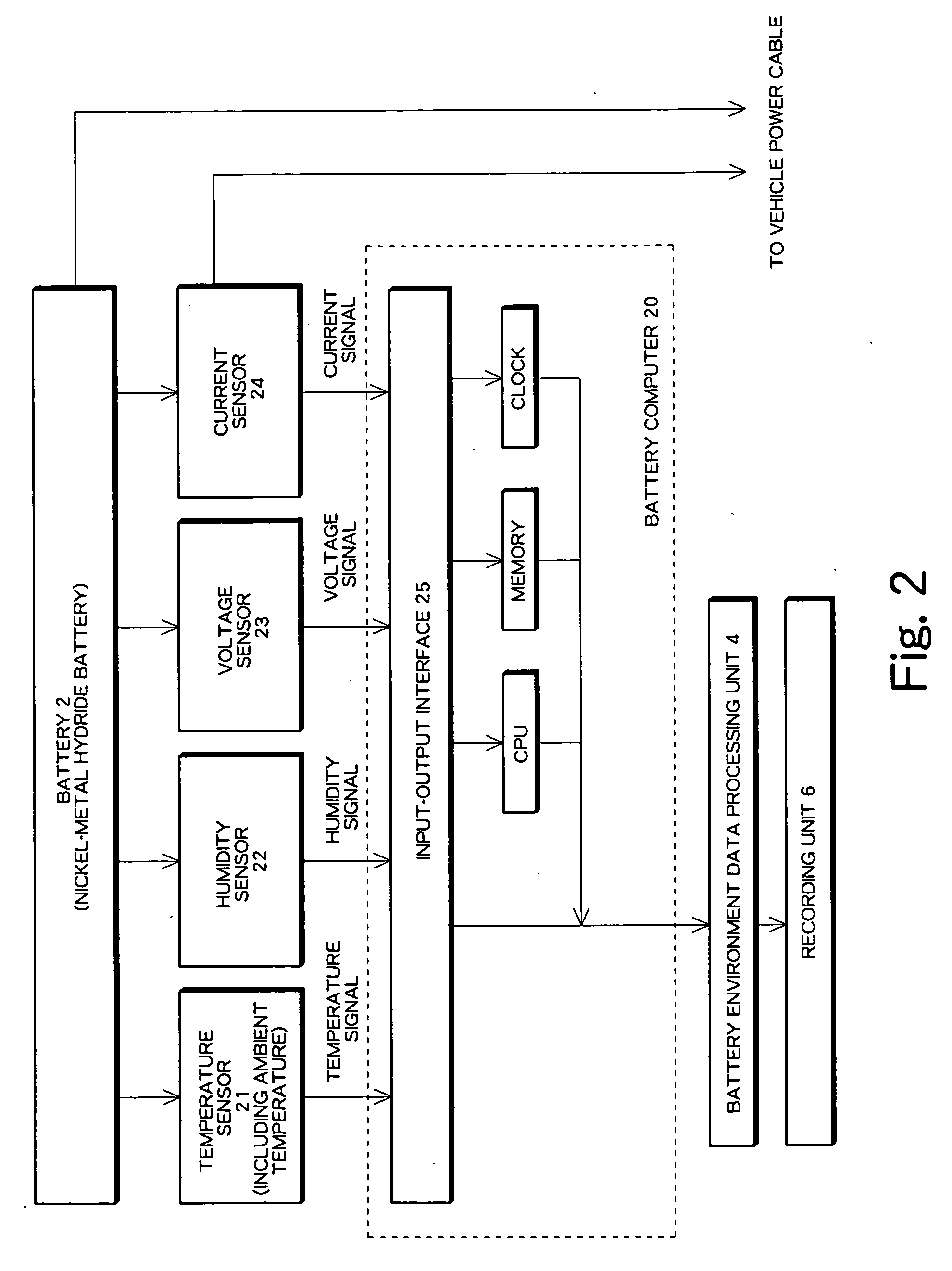
[0050] The environment data processing unit 4 measures conditions, such as temperature or humidity of the battery 2 in a powertrain, which are regarded as factors influential...


PUM


Abstract

A battery life predicting apparatus comprises a data processing unit for obtaining and processing data on a vehicle having a battery used as a power source of the vehicle, the data including battery environment data, power consumption data concerning electrical components, and vehicle running data, a recording unit for recording vehicle characteristic data and histories of the data obtained and processed, a storage for storing data concerning battery deterioration obtained in a vehicle running test, and a controller for estimating a degree of battery deterioration relative to durable years of the battery from the data recorded in the recording unit and calculating remaining life of the battery, and presents the remaining life of the battery to a driver in the display. Further, a battery life warning apparatus estimates a timing of replacing the battery and presents a level of warning to the driver.

Description

CROSS-REFERENCE TO RELATED APPLICATION [0001] This application claims the benefit of Japanese Patent Application No. 2005-229094 filed on Aug. 8, 2005, and Japanese Patent Application No. 2006-074228 filed on Mar. 17, 2006, the entirety of both of which are hereby incorporated by reference. BACKGROUND OF THE INVENTION [0002] 1. Field of the Invention [0003] The present invention relates to an apparatus for predicting remaining life of a battery mounted on a powertrain as a power source and an apparatus for warning of the end of life of the battery, and relates to a powertrain having the apparatuses installed therein. [0004] 2. Description of the Related Art [0005] Here, a term “powertrain” refers to a vehicle in which a battery is used as a part of a power source or used as the power source itself. The vehicle includes, for example, a hybrid vehicle powered by combined use of a gasoline engine and an electric motor similarly to a hybrid system, an electric vehicle powered by a fuel ...

Claims


Application Information

Patent Timeline
IPC IPC(8): H02J7/00B60L50/15
CPCG01R31/3624Y02T10/84G01R31/3679G01R31/3675G01R31/3842G01R31/392G01R31/374
Inventor UCHIDA, MASATOSHI
Owner TOYOTA JIDOSHA KK
Why Eureka
Try Eureka