High-reflectance visible-light reflector member, liquid-crystal display backlight unit employing the same, and manufacture of the high-reflectance visible-light reflector member

Inactive Publication Date: 2007-02-08
TOHOKU UNIV +1
View PDF6 Cites 16 Cited by
  • Summary
  • Abstract
  • Description
  • Claims
  • Application Information

AI Technical Summary

Benefits of technology

[0010] It is therefore an object of the present invention to provide a visible-light reflector member or reflective film having higher reflecta

Problems solved by technology

However, as the reflected light has no directivity, much light is lost when reflected by a wall or the like, resulting in poor use efficiency.
Therefore, when a diffusive reflecting plate is used in a flat-panel display having a screen width across corners of 30 inches, for example, at least twelve cold cathode fluorescent lamps (CCFLs) have to be used for providing brightness, and this leads to a disadvantage of increasi

Method used


Image

  • High-reflectance visible-light reflector member, liquid-crystal display backlight unit employing the same, and manufacture of the high-reflectance visible-light reflector member
  • High-reflectance visible-light reflector member, liquid-crystal display backlight unit employing the same, and manufacture of the high-reflectance visible-light reflector member
  • High-reflectance visible-light reflector member, liquid-crystal display backlight unit employing the same, and manufacture of the high-reflectance visible-light reflector member

Examples


first embodiment

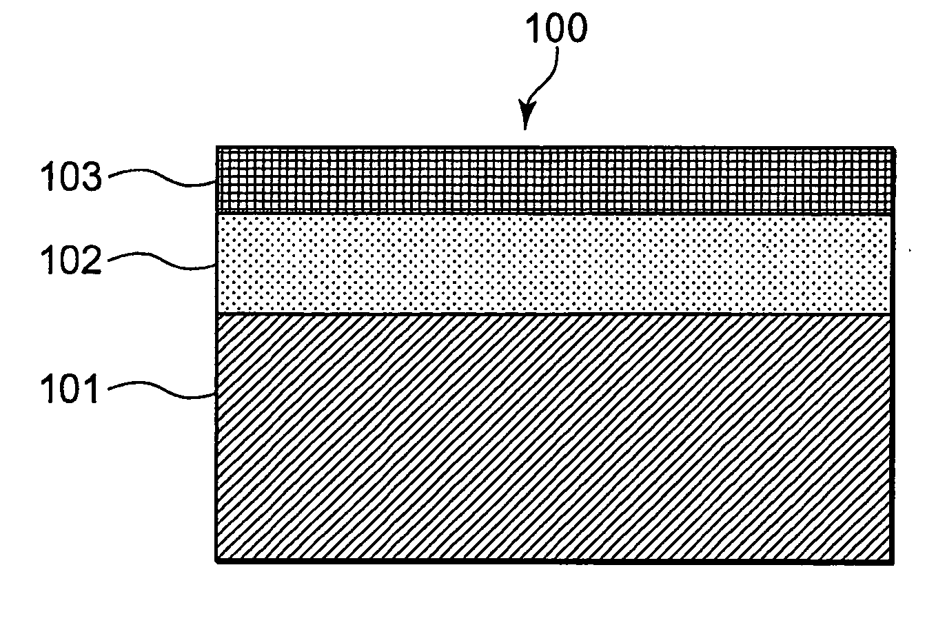
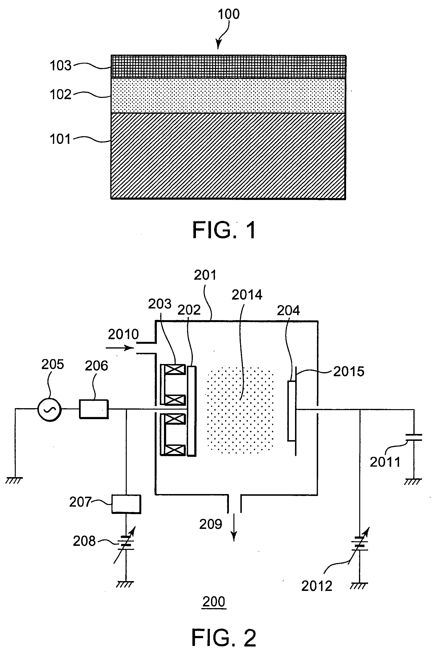
[0067] Referring to FIG. 1, a visible-light reflecting plate 100 according to a first embodiment of the present invention has a reflecting layer 102 formed on one surface of a substrate 101. The substrate 101 shown here is formed of a plastic material (specifically, a cycloolefin polymer) having a thickness of 0.7 to 2 mm. The material of the substrate is not limited to a cycloolefin polymer, but metals, glass, ceramics, and other plastic materials may be used. The size or thickness of the substrate is not limited either, but when considering the strength desired for the substrate, the thickness of the substrate is preferably 40 μm or more if the substrate is formed of a flexible material such as resin. When the substrate is formed of a metal, glass, or a ceramic material, the thickness thereof is preferably 100 μm or more. The substrate is formed by flat and / or curved surfaces. The directivity of light is defined by its substantially flat or curved portion. Therefore, the surface r...

second embodiment

[0089] A second embodiment of the present invention will be described with reference to the accompanying drawings. In order to avoid repetition, description of parts and components similar to the counterparts in the first embodiment will be omitted.

[0090] Referring to FIG. 7, a visible-light reflecting plate 700 according to the second embodiment of the present invention has a reflecting layer 702 formed on one surface of a substrate 701. The substrate 701 shown here is formed of a plastic material (specifically, a cycloolefin polymer) having a thickness of 0.7 to 2 mm. A surface protection film 703 of silicon nitride is formed on the reflecting layer 702.

[0091] The reflecting layer 702 shown here is a silver thin film having the (111) orientation as the principal plane orientation. In the second embodiment, the silver thin film having the (111) orientation as the principal plane orientation was formed by using the RF-DC-combined sputtering apparatus shown in FIG. 2. Xenon gas ins...

third embodiment

[0096] A third embodiment of the present invention will now be described. In order to avoid repetition, description of parts and components similar to the counterparts in the first and second embodiments is omitted.

[0097] As shown in FIG. 12, a visible-light reflecting plate 1200 according the third embodiment of the present invention has a reflecting layer 1202 formed on one surface of a substrate 1201. The substrate 1201 shown here is formed of a plastic material (specifically, a cycloolefin polymer) having a thickness of 0.7 to 2 mm. A surface protection film 1303 of silicon nitride is formed on the reflecting layer 1202.

[0098] The reflecting layer 1202 shown here is a silver thin film having the (111) orientation as the principal plane orientation. The silver thin film having the (111) orientation as the principal plane orientation was formed by using the RF-DC-combined sputtering apparatus shown in FIG. 2. In this embodiment, after the substrate was transferred into the proce...


PUM

PropertyMeasurementUnit
Fractionaaaaaaaaaa
Thicknessaaaaaaaaaa
Thicknessaaaaaaaaaa

Abstract

A reflector member of the present invention includes a silver thin film formed on a substrate and a silicon nitride protection film formed on the silver thin film. The silver thin film has the (111) orientation as the principal plane orientation. Preferably, 99% or more of the silver thin film has the (111) orientation as the principal plane orientation. The thickness of the silver thin film is in a range of 100 nm to 350 nm.

Description

[0001] This application claims priority to prior Japanese patent application JP 2005-215404, the disclosure of which is incorporated herein by reference. BACKGROUND OF THE INVENTION [0002] The present invention relates to a reflector member for reflecting visible light, and in particular to a visible-light reflector member suitable as a reflecting plate for use in a backlight unit of a large-size flat-panel liquid-crystal display having a screen width across corners of 28 inches or greater, or as a reflector member for use in a rear projection television. [0003] The reflecting plates for reflecting visible light includes diffusive reflecting plates applied with white paint or those containing diffusion beads, polished metal plates, and reflecting plates fabricated by depositing metallic atoms on a substrate to form thin films. [0004] These visible-light reflecting plates are used in a variety of applications, such as reflecting plates for liquid crystal display backlight units or re...

Claims


Application Information

Patent Timeline
IPC IPC(8): G02B1/10F21V9/04G02F1/1335B32B17/06C23C14/00C23C14/32
CPCC23C14/022C23C14/205C23C14/345C23C14/584C23C16/0281C23C28/36G02B5/0858G02B6/0055C23C28/322C23C28/34C23C16/345G02F1/1335
Inventor OHMI, TADAHIROGOTO, TETSUYASEKI, NOBUAKIIKEDA, SATOSHINIIKURA, KOUICHI
Owner TOHOKU UNIV
Why Eureka
Try Eureka