
Light transmitted assay beads

a light-transmitted assay and beads technology, applied in the field of beads, can solve the problems of insufficient sample amounts or non-uniform distribution over the chip surface, incomplete reactions or very long reaction time, and mechanical contact printing is not very attractiv

Active Publication Date: 2007-02-15
APPLIED BIOCODE
View PDF9 Cites 59 Cited by
  • Summary
  • Abstract
  • Description
  • Claims
  • Application Information

AI Technical Summary

Benefits of technology

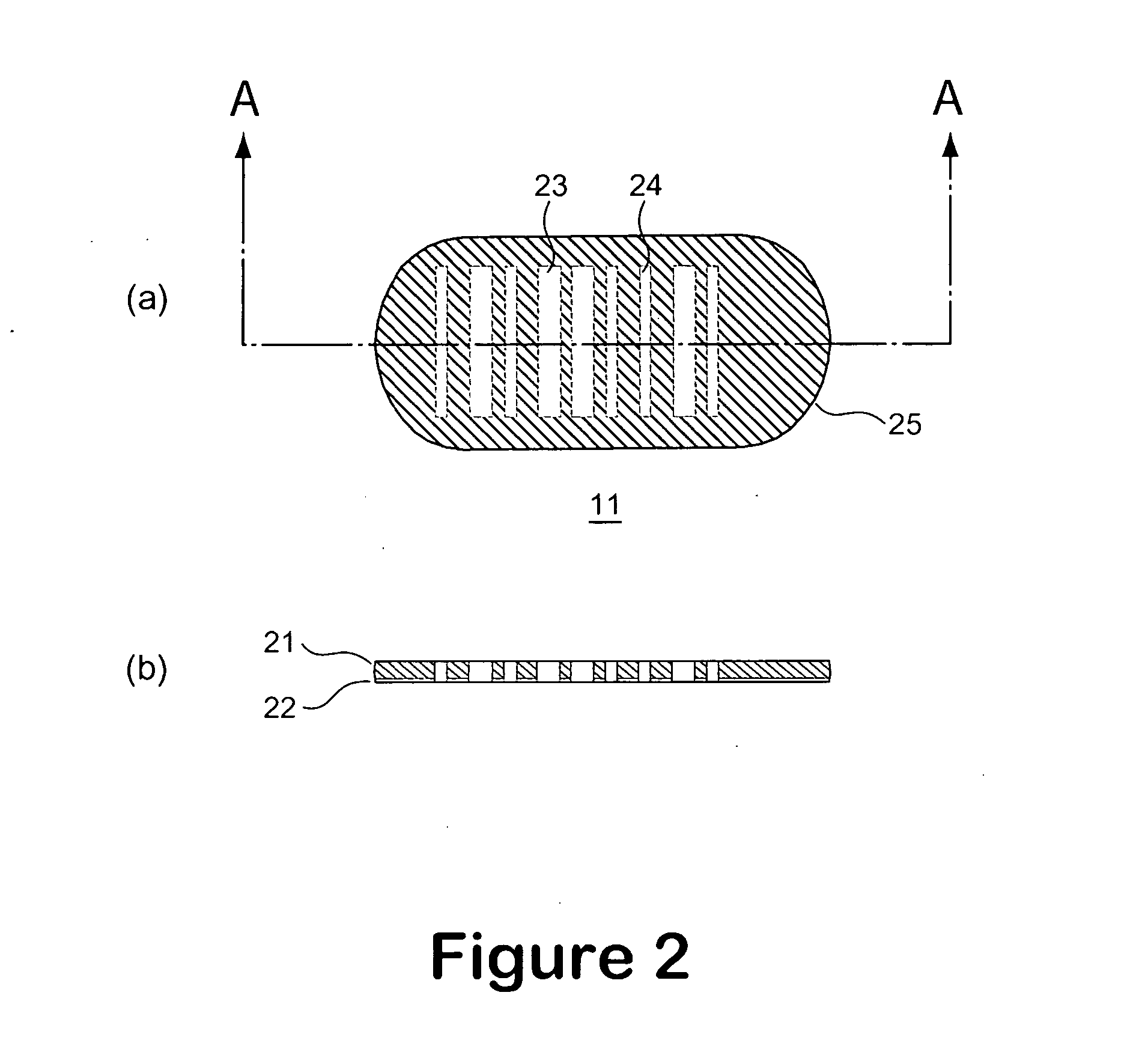
[0015] In one embodiment, the coded bead is provided with a reflective thin film, (e.g., plating or coating the coded bead with a metal thin film, or providing an intermediate layer of metal thin film) to improve contrast and optical efficiency for image recognition for decoding.
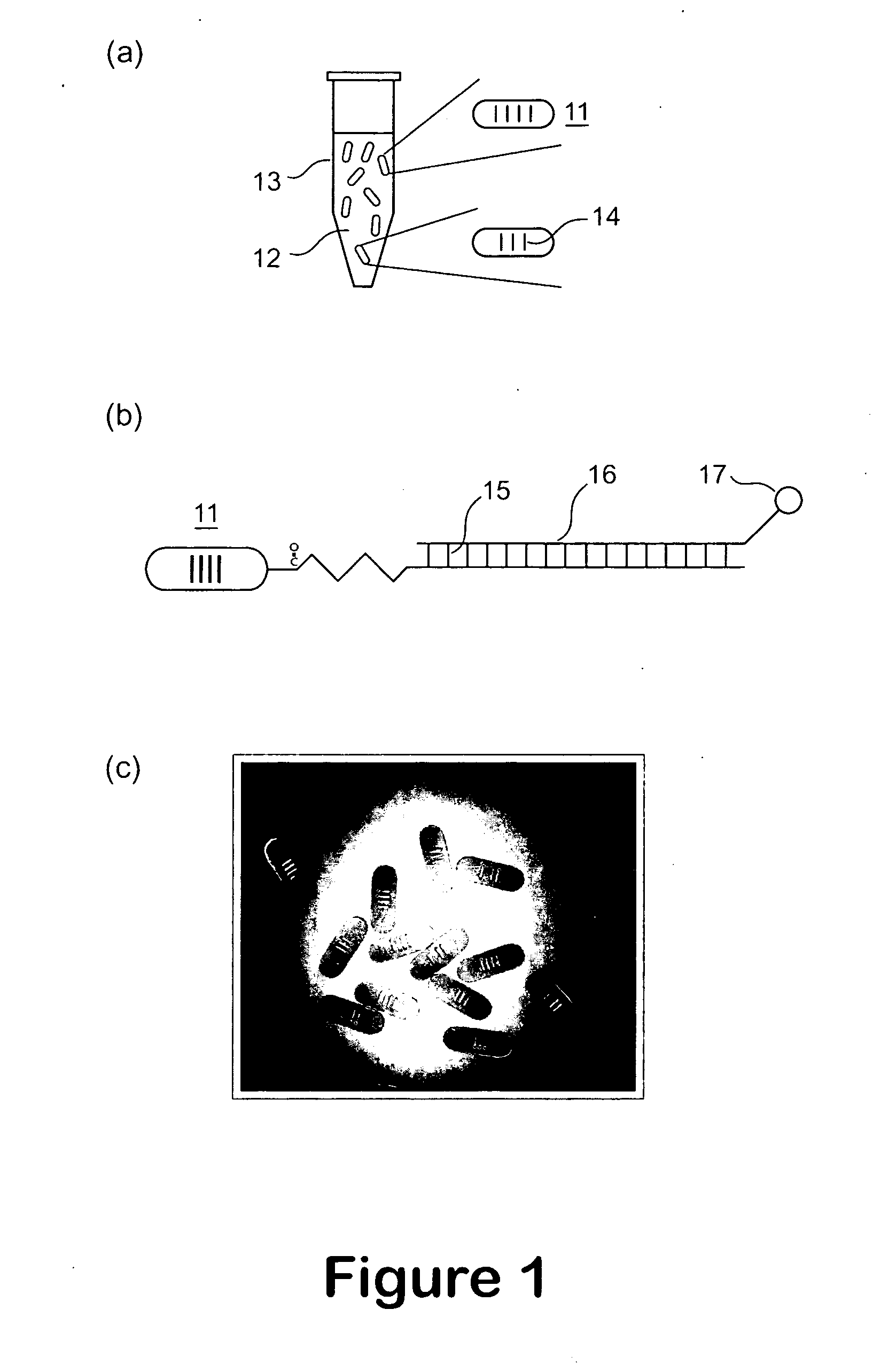
[0018] The identity of the bead may be associated with other properties and / or characteristics. In another aspect of the present invention, the coded bead is coated or immobilized with a biological and / or chemical substance, as a specific capture or probe to effect a desired bioassay or identification application. A plurality of beads may be applied to conduct multiplexed bioassays. For example the bead may be functionalized with a material selected from the group consisting of proteins, nucleic acids, small molecules, organic chemicals, inorganic chemicals, and combinations thereof, allowing for the possibility of multiplexed assays in homogeneous or heterogeneous media, using micro-volume samples.

Problems solved by technology

However, mechanical contact printing is not very attractive because it is printed one spot per contact that results in relatively large printing variations from spot to spot or batch to batch, inconsistent spot morphology, misprinting, and slide surface variations, all of which are undesirable for DNA microarray analysis.
Further, distributing a small volume of liquid samples over a relatively large chip surface often encounters the problems of insufficient sample amounts or non-uniform distribution over the chip surface.
These problems can cause incomplete reactions or very long reaction time.
The problems of reflection configuration are (1) it is difficult to setup the collection optics in proper position, especially when the beads are in micrometer scale, and (2) the light collection efficiency is poor and the barcode contrast is low, especially when micro beads are in the micro flow system.
The flow scatters light, which interferes with optical reflection or emissive detection.
Further, fluorescent beads, the spectral range and the possible number of spectrally distinguishable labels, however, often limit the potential number of code variations.
In addition, the validity of the coding signatures is another serious concern, since the incorporated coding elements in some cases may be lost; photo bleached, or interfered spectrally with the analytical signals.
In the case of multi-metal (Au, Pt, Ni, Ag, etc) color micro rods, the encoding scheme suffers from the difficulty of manufacturing and the number of colors, based on different metal materials, is limited.
Although high speed camera is available for capturing bar code images, pattern recognition is a slow and time consuming process.
Therefore, it is difficult to identify hundreds or thousands of beads in a short time to improve throughput.

Method used


Image

  • Light transmitted assay beads
  • Light transmitted assay beads
  • Light transmitted assay beads

Examples


Embodiment Construction

[0026] The present description is of the best presently contemplated mode of carrying out the invention. This description is made for the purpose of illustrating the general principles of the invention and should not be taken in a limiting sense. The scope of the invention is best determined by reference to the appended claims.

[0027] For purposes of illustrating the principles of the present invention and not by limitation, the present invention is described herein below by reference to a micro bead that is in the shape of a pallet, and by reference to bioanalysis. However, it is understood that the present invention is equally applicable to micro beads of other overall geometries, and which are applied for other applications requiring identification based on the identity of the beads, without departing from the scope and spirit of the present invention. To facilitate discussion below, the micro bead of the present invention is referred to as a LITAB, which stands for a light trans...


PUM

PropertyMeasurementUnit
Lengthaaaaaaaaaa
Widthaaaaaaaaaa
Widthaaaaaaaaaa

Abstract

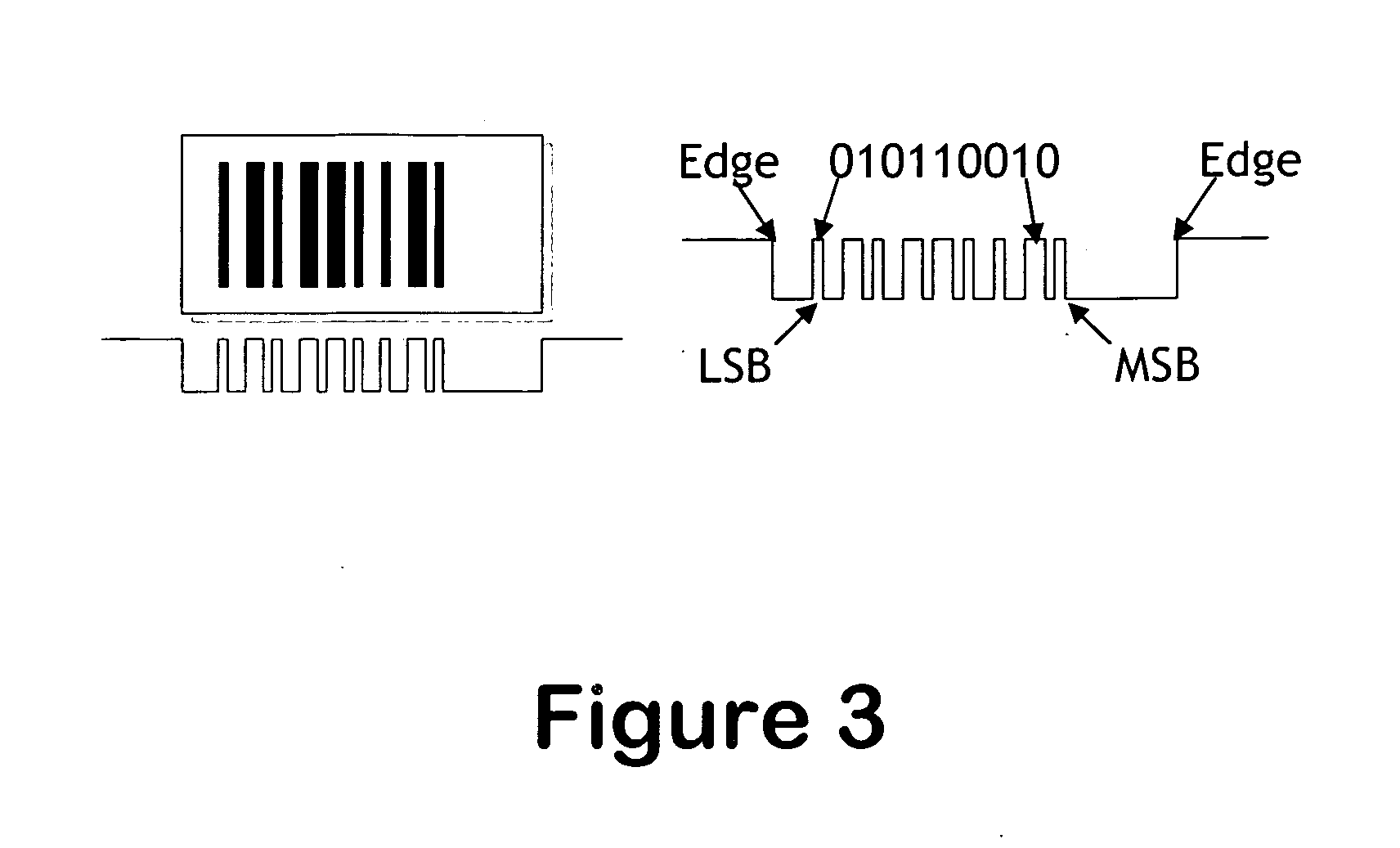
A micro bead having a digitally coded structure that is partially transmissive and opaque to light. The pattern of transmitted light is determined by to decode the bead. The coded bead may be structured a series of alternating light transmissive and opaque sections, with relative positions, widths and spacing resembling a 1D or 2D bar code image. To decode the image, the alternating transmissive and opaque sections of the body are scanned in analogous fashion to bar code scanning. The coded bead may be coated or immobilized with a capture or probe to effect a desired bioassay. The coded bead may include a paramagnetic material. A bioanalysis system conducts high throughput bioanalysis using the coded bead, including a reaction detection zone and a decoding zone.

Description

[0001] This application claims the benefit of the priority of Provisional Patent Application No. 60 / 706,896, which was filed Aug. 9, 2005. This provisional application is fully incorporated by reference, as if fully set forth herein. All other publications and U.S. patent applications disclosed herein below are also incorporated by reference, as if fully set forth herein.BACKGROUND OF THE INVENTION [0002] 1. Field of the Invention [0003] The invention relates generally to assay beads and methods for use thereof to carry out bioassays, and more particularly multiplexed bioassays using micro-volume samples, such as protein and nucleic acid analysis. [0004] 2. Description of Related Art [0005] As current research in genomics and proteomics produces more multiplexed data, there is a need for technologies that can rapidly screen a large number of nucleic acids and proteins in a very small volume of samples. Microarray, DNA chips, and protein chips have drawn a great deal of commercial in...

Claims


Application Information

Patent Timeline
IPC IPC(8): C12Q1/68C12M1/34G01N33/551
CPCC12Q1/6813C12Q1/6846G01N33/54313G01N33/54326C12Q2563/107C12Q2563/155Y10S977/704Y10S977/776
Inventor HO, WINSTON Z.
Owner APPLIED BIOCODE
Learn More