
Microarray synthesis instrument and method

a synthesis instrument and microarray technology, applied in the field of microarray synthesis instruments and methods, can solve the problems of long processing time, relatively high cost and long processing time, and the conventional sequencing of dna using electrophoresis is typically laborious and time-consuming, and achieves the effect of reducing reflected light, reducing the number of unfavorable reactions, and reducing the cost of fixed processing tim

Inactive Publication Date: 2007-02-15
ROCHE NIMBLEGEN
View PDF14 Cites 37 Cited by
  • Summary
  • Abstract
  • Description
  • Claims
  • Application Information

AI Technical Summary

Benefits of technology

The invention is a flow cell for a microarray synthesis instrument that reduces reflected light and unwanted reactions during the synthesis of microarrays. It achieves this by selecting the material of the block and the medium in the flow cell to have the same index of refraction, which limits stray light. This results in more efficient use of light in the instrument and improved quality of the microarrays produced.

Problems solved by technology

The conventional sequencing of DNA using electrophoresis is typically laborious and time consuming.
A disadvantage of both of these approaches is that four different lithographic masks are needed for each monomeric base, and the total number of different masks required are thus four times the length of the DNA probe sequences to be synthesized.
The high cost of producing the many precision photolithographic masks that are required, and the multiple processing steps required for repositioning of the masks for every exposure, contribute to relatively high costs and lengthy processing times.
A similar problem exists for synthesis of diverse sequences of other types of oligomers such as polypeptides, which is useful for determining binding affinity in screening studies.
However, the large number of lithographic masks needed in the synthesis makes the fixed cost for this process relatively high and the processing time lengthy.
Light that is misdirected, inadvertently reflected or otherwise directly randomly inside the instrument, herein referred to as “stray light,” can adversely affect the overall accuracy and fidelity of the arrays made by the instrument.
Excess stray light can lead to the de-protection of areas of the array other than the ones intended to be de-protected, and thus cause errors in the synthesis of probes.
This problem cannot be well-controlled in a photolithographic process, where the use of masks interposed between the light source and the array synthesis cell inherently causes refracted light in some amount to be direct where it is not intended.

Method used


Image

  • Microarray synthesis instrument and method
  • Microarray synthesis instrument and method
  • Microarray synthesis instrument and method

Examples


Embodiment Construction

[0025] The present invention is an improvement to the type of maskless microarray synthesizer described in the above-mentioned PCT Patent Application No. 99 / 42813, the disclosure of which is hereby incorporated by reference.

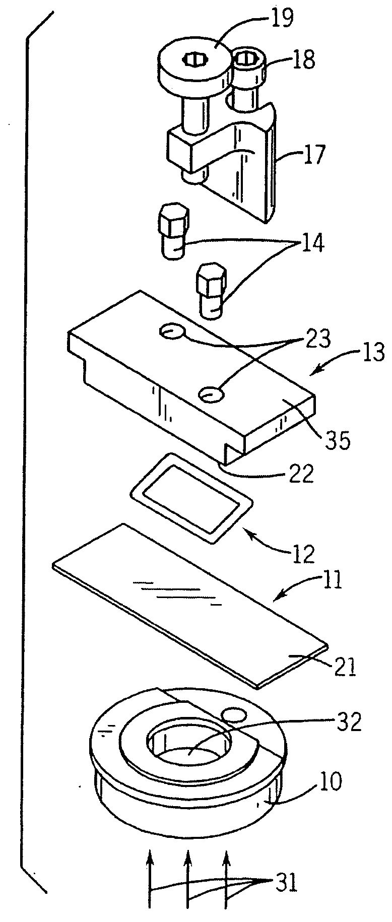
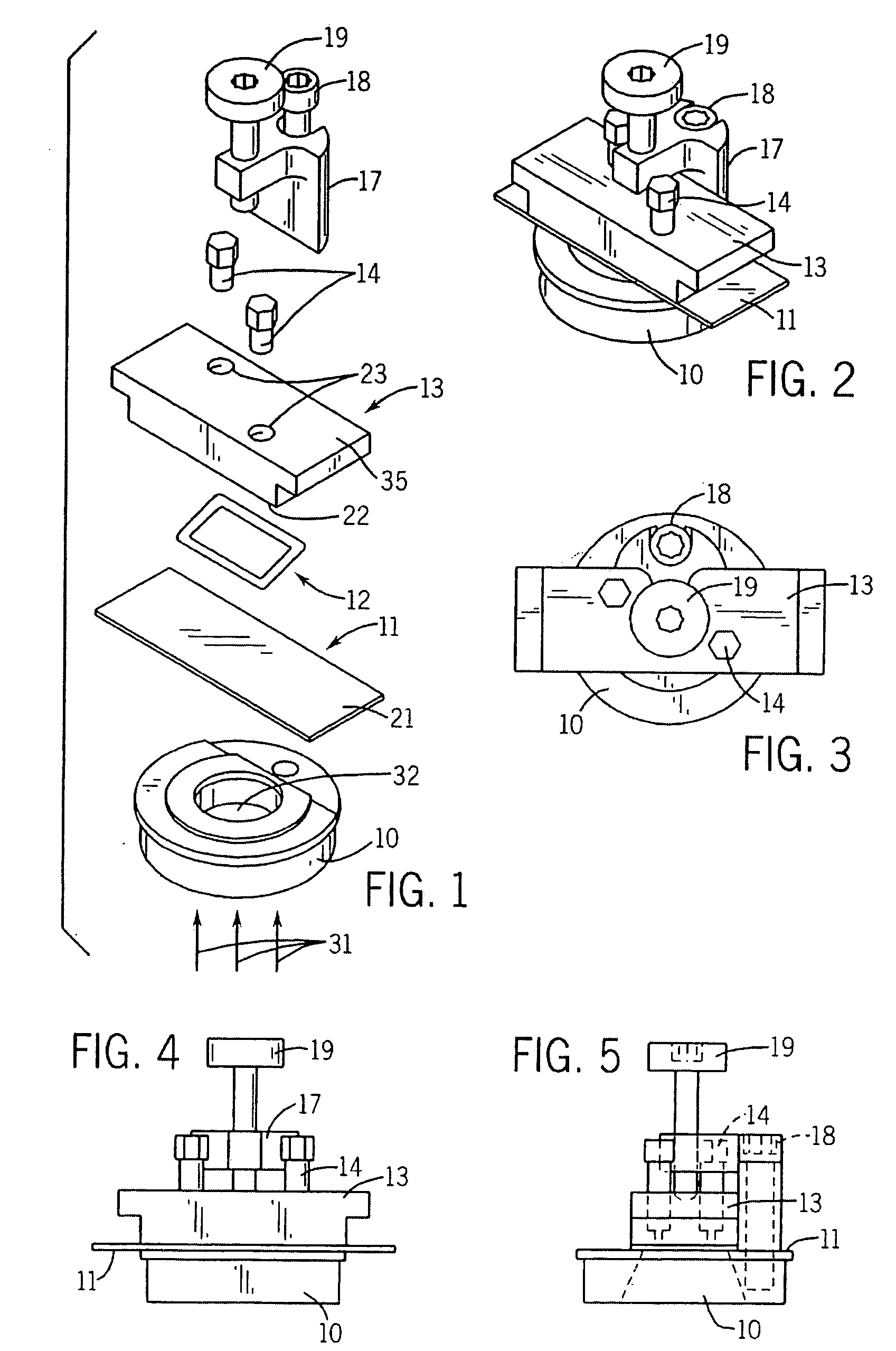
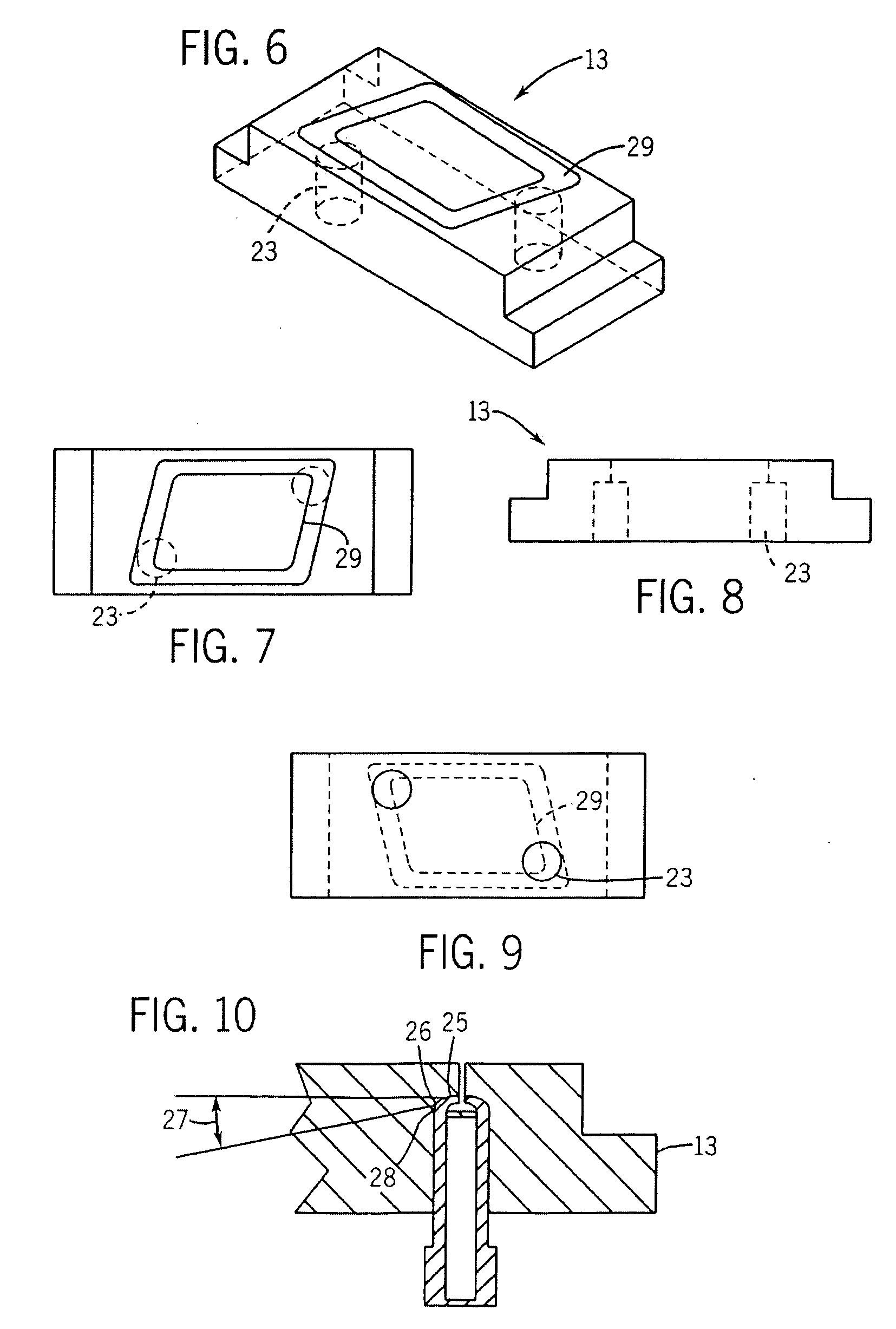
[0026] In making a maskless array synthesizer, deposition of nucleic acids is determined by light deprotection of areas of the array. Since the application of light energy determines where the nucleic acids are deposited in the array, the precise control of light is a critical parameter in the quality of the array made. In fact, in making instruments intended to produce high quality arrays with optimal sequence uniformity and consistence in the DNA probes, the control of “stray light” has been found to be among the most important parameters. Stray light, as used here, refers to light which is incident onto areas of the array where is it not desired. Said in other words, stray light is light incident on a cell of the array which is supposed to be unlit at a parti...


PUM

PropertyMeasurementUnit
wavelengthsaaaaaaaaaa
refractive indexaaaaaaaaaa

Abstract

During the light illumination period of a monomer addition cycle in synthesizing an DNA microarray, undesirable reflections of illumination light from various interfaces that the illumination light passes through near the synthesis surface of the substrate may reduce the light-dark contrast, and negatively affect the precision and resolution of the microarray synthesis. The present invention provides an flow cell that reduces the undesired reflections by constructing certain flow cell structures with materials that have similar refractive indexes as that of the solution that is in the oligomer synthesis chamber during the illumination period and / or constructing certain flow cell structures or covering the structures with a layer of a material that has a high extinction coefficient.

Description

CROSS-REFERENCE TO RELATED APPLICATIONS [0001] This application is a continuation of U.S. application Ser. No. 10 / 062,918, filed Feb. 1, 2002, incorporated herein by reference as if set forth in its entirety.STATEMENT REGARDING FEDERALLY SPONSORED RESEARCH OR DEVELOPMENT [0002] Not applicable. BACKGROUND OF THE INVENTION [0003] The sequencing of deoxyribonucleic acid (DNA) is a fundamental tool of modern biology and is conventionally carried out in various ways, commonly by processes which separate DNA segments by electrophoresis. See, e.g., “DNA Sequencing,” Current Protocols In Molecular Biology, Vol. 1, Chapter 7 (1995). The sequencing of several important genomes has already been completed (e.g., yeast, E. coli), and work is proceeding on the sequencing of other genomes of medical and agricultural importance (e.g., human, C. elegans, Arabidopsis). In the medical context, it will be necessary to “re-sequence” the genome of large numbers of human individuals to determine which gen...

Claims


Application Information

Patent Timeline
Patent Type & Authority Applications(United States)
IPC IPC(8): C12M1/34B01J19/00G01N33/53B01J19/12C12Q1/68C40B40/06C40B50/14C40B60/14G01N37/00
CPCB01J19/0046C40B60/14B01J2219/00353B01J2219/00436B01J2219/00439B01J2219/0045B01J2219/00527B01J2219/00585B01J2219/00596B01J2219/00605B01J2219/00612B01J2219/00637B01J2219/00659B01J2219/00675B01J2219/00711B01J2219/00722B82Y30/00C40B40/06C40B50/14B01J2219/00286
Inventor GREEN, ROLANDPITAS, ALANCERRINA, FRANCESCO
Owner ROCHE NIMBLEGEN
Learn More