
Vibration monitoring

a vibration monitoring and vibration technology, applied in the direction of liquid/fluent solid measurement, machines/engines, instruments, etc., can solve the problems of drill stem clogging, inconvenient and potentially hazardous drilling, coke formation, etc., to prevent foamover accurately and efficiently

Inactive Publication Date: 2007-02-15
CURTISS WRIGHT FLOW CONTROL CORP
View PDF75 Cites 28 Cited by
  • Summary
  • Abstract
  • Description
  • Claims
  • Application Information

AI Technical Summary

Benefits of technology

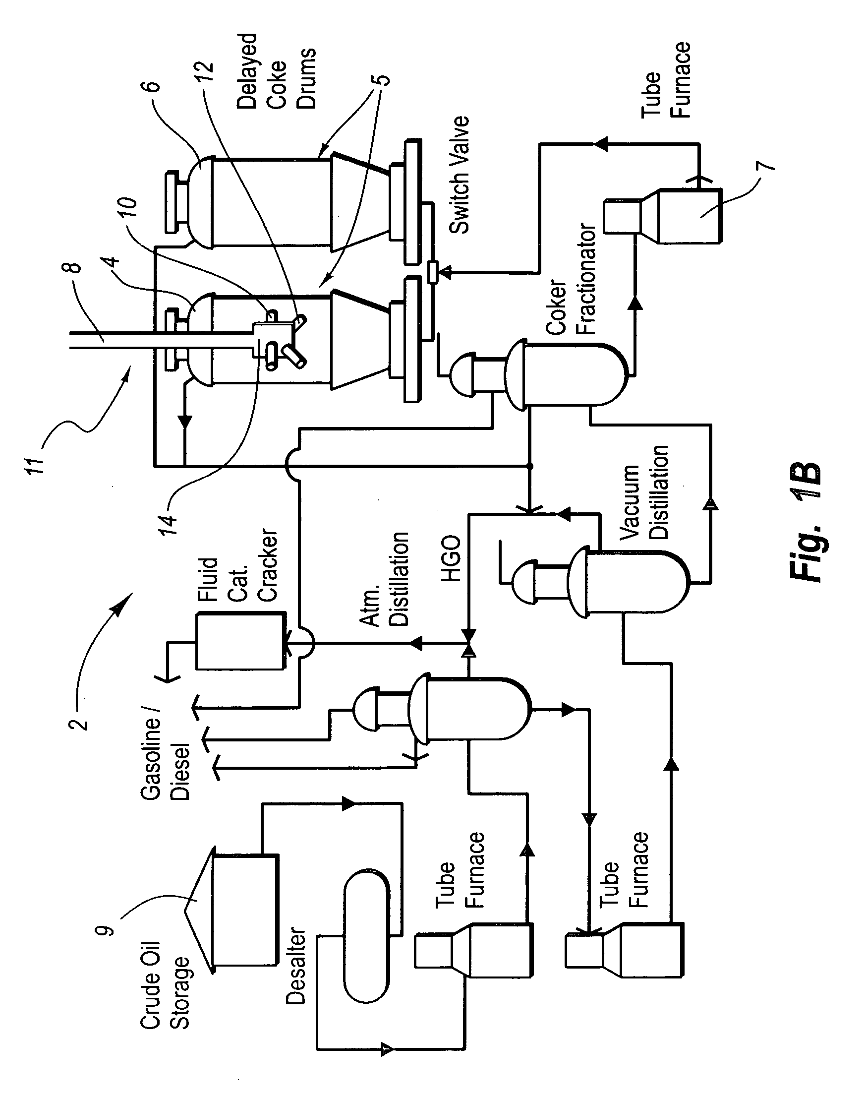
[0014] The present invention relates to systems for remotely monitoring the status of a cutting tool during delayed decoker unit operation, and systems for remotely monitoring the level of coke or foam in a drum during the coking process. The former systems relate to systems for allowing operators involved in removing solid carbonaceous residue, referred to as “coke,” from large cylindrical vessels called coke drums to determine the status of the decoking operation from a remote location. The latter systems relate to systems for allowing operators involved in monitoring coke and / or foam levels in the drum during coking to more accurately and efficiently prevent foamovers and disastrous results resulting from coke levels from rising too high.
[0020] Preferred embodiments of the invention relate to a system that allows an operator to remotely detect the status of a cutting tool while cutting coke within a coke drum, and to remotely detect when the tool has switched between the “boring” and the “cutting” modes, while cutting coke within a coke drum reliably, and without raising the drill bit out of the coke drum for mechanical alteration or inspection.

Problems solved by technology

The unvaporized portion of the heated heavy feed settles out in the coke drum, where the combined effect of retention time and temperature causes the formation of coke.
This takes time, is inconvenient and is potentially hazardous.
Automatic switching within the coke drum oftentimes results in drill stem clogging, which still requires the drill stem to be removed for cleaning prior to completing the coke-cutting process.
Often, in automatic switching systems, it is difficult to determine whether or not the drill stem is in cutting or boring mode, because the entire change takes place within the drum.
Mistakes in identifying whether the high pressure water is cutting or boring lead to serious accidents.
Thus, coke-cutting efficiency is compromised because the switching operator does not know whether or not the cutting process is complete or simply clogged.
If the hydro-cutting system is not shut off before the drill stem is raised out of the top drum opening, operators are exposed to the high pressure water jet and serious injuries, including dismemberment, occur.
Thus, operators are exposed to significant safety hazards from exposure to high pressure water jets in close proximity to the vessel being decoked, when manually changing the cutting head from the boring to cutting mode or when an operator has not accurately been able to access whether the head is cutting, boring or off.
Another problem encountered during the coking process is the difficultly in determining the level of coke at the top of the drum.
Similarly, the level of foam located on top of the coke is also difficult to determine.
Numerous serious problems, known to those skilled in the art, can occur if the coke level gets too high or if the foam gets into the feed lines connected to the drum.

Method used


Image

  • Vibration monitoring
  • Vibration monitoring
  • Vibration monitoring

Examples


Embodiment Construction

[0014] The present invention relates to systems for remotely monitoring the status of a cutting tool during delayed decoker unit operation, and systems for remotely monitoring the level of coke or foam in a drum during the coking process. The former systems relate to systems for allowing operators involved in removing solid carbonaceous residue, referred to as “coke,” from large cylindrical vessels called coke drums to determine the status of the decoking operation from a remote location. The latter systems relate to systems for allowing operators involved in monitoring coke and / or foam levels in the drum during coking to more accurately and efficiently prevent foamovers and disastrous results resulting from coke levels from rising too high.

[0015] Some embodiments relate to continuous monitoring and detection of reduced material thickness in elbows and pipes which are carrying high temperature and / or high pressure fluids or gases.

[0016] In some embodiments, the monitoring systems ...


PUM


Abstract

Systems, devices, and methods for monitoring the status of a cutting tool during delayed decoker unit operation, and systems for remotely monitoring the level of coke or foam in a drum during the coking process. One or more sensors or accelerometers is coupled to a location in a delayed coking unit operation to read vibrations emanating from the component that the respective accelerometers are located on. Vibrational data is transmitted to a computer system that manipulates the data to provide useful information that an operator of a delayed coking unit operation may view.

Description

RELATED APPLICATIONS [0001] This patent application claims priority to: (1) U.S. Provisional patent application Ser. No. 60 / 707,929, filed Aug. 12, 2005 and entitled VIBRATION MONITORING DEVICE; and (2) U.S. Provisional patent application Ser. No. 60 / 777,621, filed Feb. 28, 2006 and entitled VIBRATION MONITORING SYSTEM.BACKGROUND [0002] 1. Field of the Invention [0003] The present invention relates to vibration monitoring devices and methods for using the same. Specifically, the present invention relates to determining the level of coke or coke byproducts inside a coker drum and to noninvasive signature recognition systems using accelerometers and mathematical algorithms for signature detection. [0004] 2. Background Information [0005] Petroleum refining operations in which crude oil is processed frequently produce residual oils. Many oil refineries recover valuable products from heavy residual hydrocarbons. Residual oil, when processed in a delayed coker, is heated in a furnace to a...

Claims


Application Information

Patent Timeline
Patent Type & Authority Applications(United States)
IPC IPC(8): G01H1/00G01M99/00
CPCG01H1/14C10B41/04
Inventor BORAH, FREDERICLEIB, ANTHONY JR.FKIARAS, GEORGELAH, RUBEN F.
Owner CURTISS WRIGHT FLOW CONTROL CORP
Learn More