
Method And System For Assessing Quality Of Spot Welds

a spot weld quality and method technology, applied in the field of method and system for assessing can solve the problems of not solving the overall solution, more difficult to control the quality of spot welds, and quality control of spot welds, so as to facilitate on-line, non-destructive inspection of spot welds

Inactive Publication Date: 2007-02-15
FCA US
View PDF36 Cites 182 Cited by
  • Summary
  • Abstract
  • Description
  • Claims
  • Application Information

AI Technical Summary

Benefits of technology

The patent describes a new method and system for inspecting the quality of spot welds in real-time using acoustic technology. The system can detect any inconsistent weld strength and provide feedback to the welding unit, reducing the number of spot welds and manufacturing costs. The method and apparatus use statistical and neural network methods to accurately predict weld quality and perform inspections based on the internal structure of the welds. Overall, the invention provides a closed-loop feedback quality-advisor system that improves the design process and ensures the integrity of any given weld.

Problems solved by technology

As these industries grow, the quality control of spot welds becomes an important issue for manufacturers eager to improve their output capacity and product quality.
Furthermore, the intricate relationship between these factors makes it more difficult to control the quality of spot welds.
Numerous efforts have been made to improve weld quality through different approaches, nevertheless, most of them are not overall solutions due to the lack of adequate equipment and efficient algorithms to inspect these improvements.
But these weld quality indicators are vague due to the insufficient quantified description.
More importantly, the weld quality indicators are mostly for visual inspection and destructive testing, which are typically separately conducted.
Thus, present weld quality control does not take into account the combined effect of those indicators.
Furthermore, the true quality of the spot weld, i.e., its strength, is only presumed by off-line destructive sample tests.
Acoustic methods, however, are not flawless.
The most significant limitations include the requirements of a propagating medium, or couplant fluid, which is required for acoustic wave propagation between the acoustic probe and the test specimen, and skillful operators for operating the devices and analyzing the acoustic information.
While the first limitation is typically overcome because the materials for joining in the automotive and aerospace industries are usually galvanized or coated and thus will not be damaged by any couplant fluid, the second limitation—the need for skillful operators—is much more significant.
The on-line inspection of spot welds is very difficult because it is not economical to train every worker in the plant to be a tester / analyzerloperator.
More importantly, the acoustic method, by its very nature, limits the practicality of an on-line inspection.
While the C-scan provides the richest information, and is therefore more desirable for quality control purposes, it is also the most time consuming scan, and therefore difficult to perform on-line.
Conventional quality control devices for spot welding cannot perform on-line inspection of spot welds, nor can they provide feedback to the welding control system.
While it is imperative to combine the idea of on-line quality inspection with closed-loop feedback control in a robust spot-welding control system, there is not an acoustic method capable of manipulating real-time control and on-line quality inspection.

Method used


Image

  • Method And System For Assessing Quality Of Spot Welds
  • Method And System For Assessing Quality Of Spot Welds
  • Method And System For Assessing Quality Of Spot Welds

Examples


examples

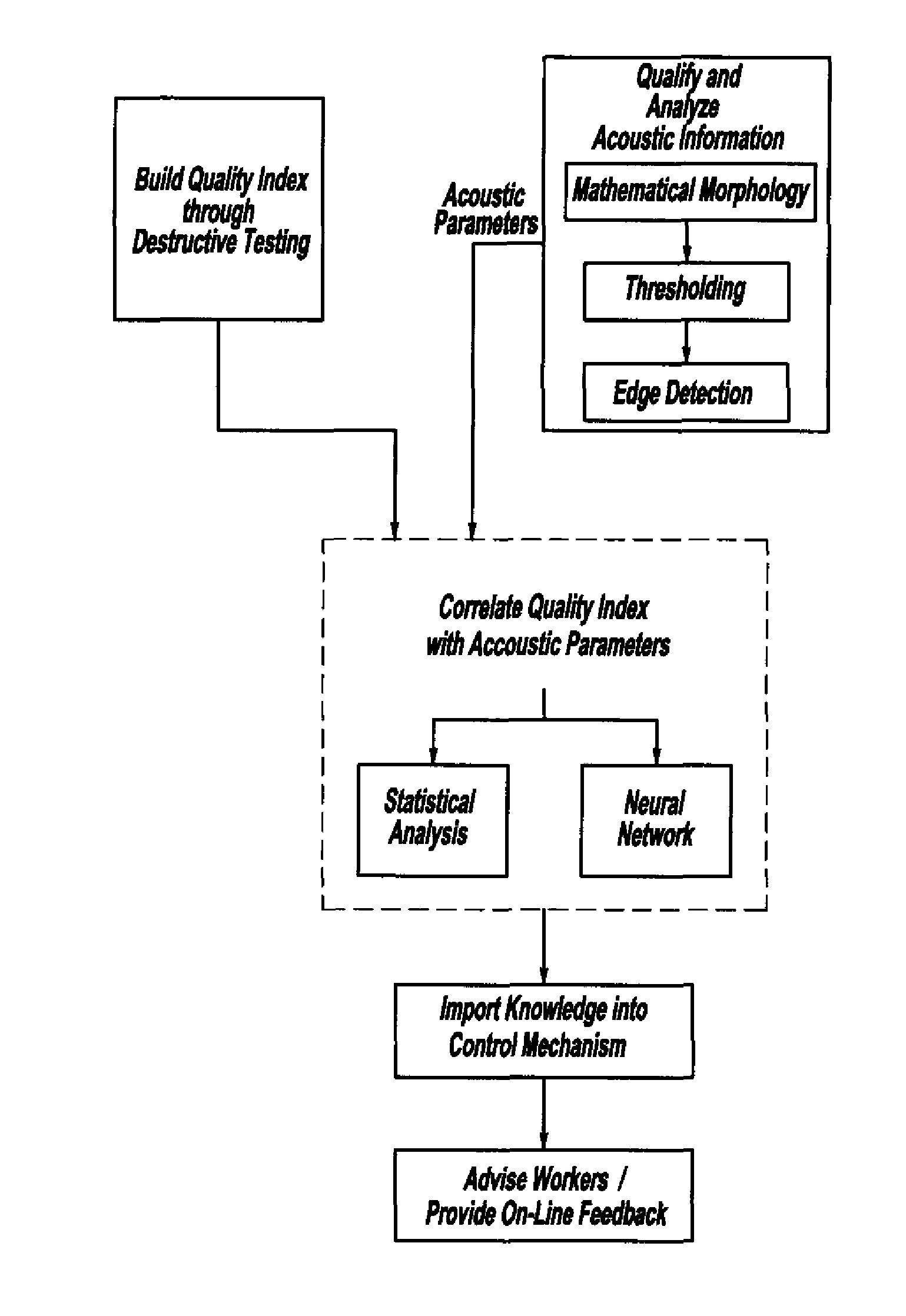
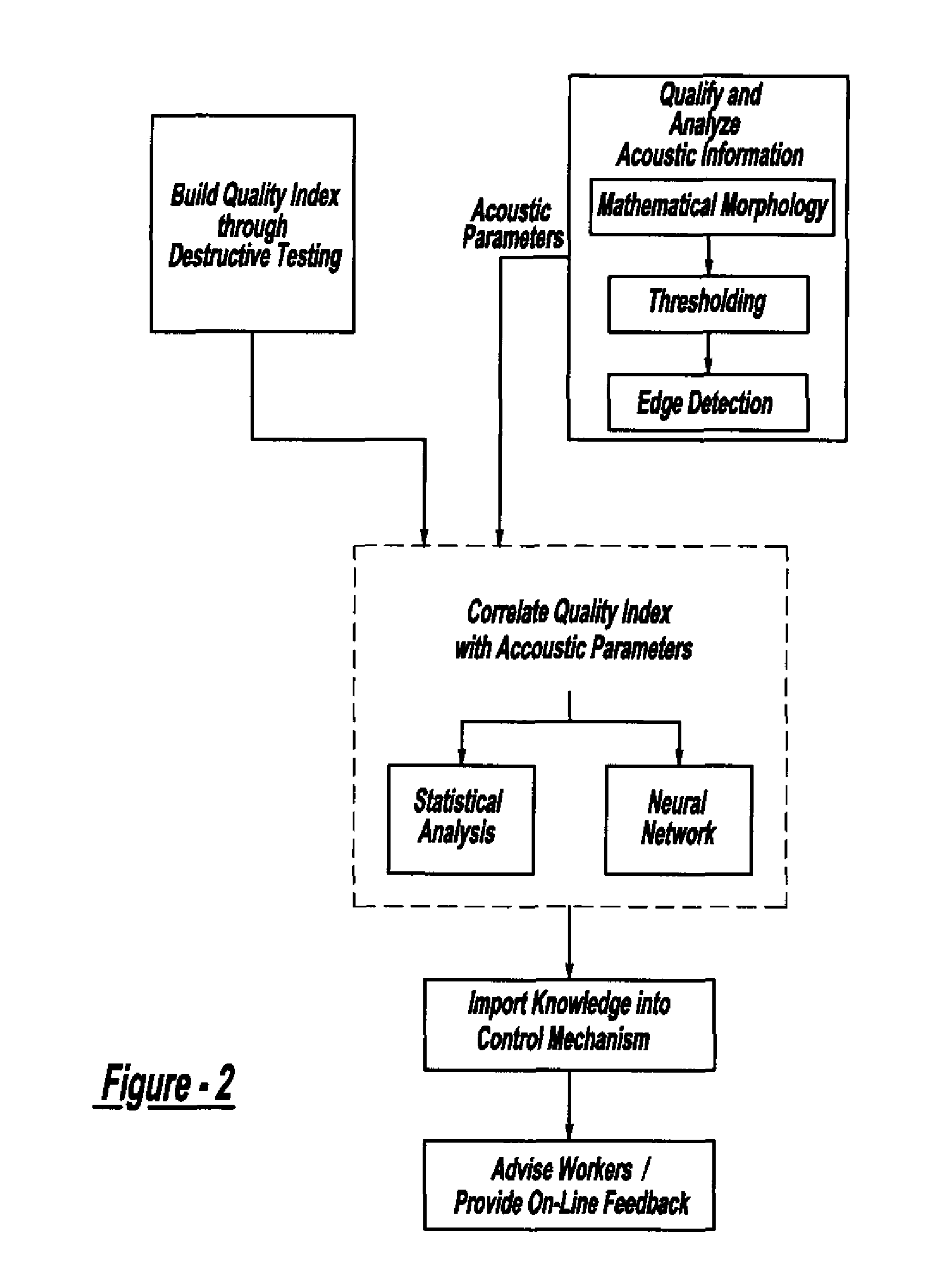
[0099] The above system and methods will now be illustrated with several examples. These examples include examined specimens produced under carefully controlled welding parameters (welding current, electrode pressure, and holding time) and identical metal conditions (e.g., surface coating, thickness). Due to the continuous hardware improvement, weld specimens were separated into three groups chronologically. The first group, with C-scan images as the results, was examined earlier by ultra-Short Pulse Scanning reflection Acoustic Microscope (SPSAM). The quality of these specimens was certified by experts from the best to the worst as setup, nominal, minimum, less than minimum, and stick weld, respectively. The minimum quality is the bottom line of an accepted weld. The second group, with C-scan images as the results, was examined by SPSAM as well. This group was peel tested and served as the verification group to test the Artificial Neural networks (ANN) model built by Group One. The...


PUM

PropertyMeasurementUnit
frequenciesaaaaaaaaaa
ultrasound imageaaaaaaaaaa
weightaaaaaaaaaa

Abstract

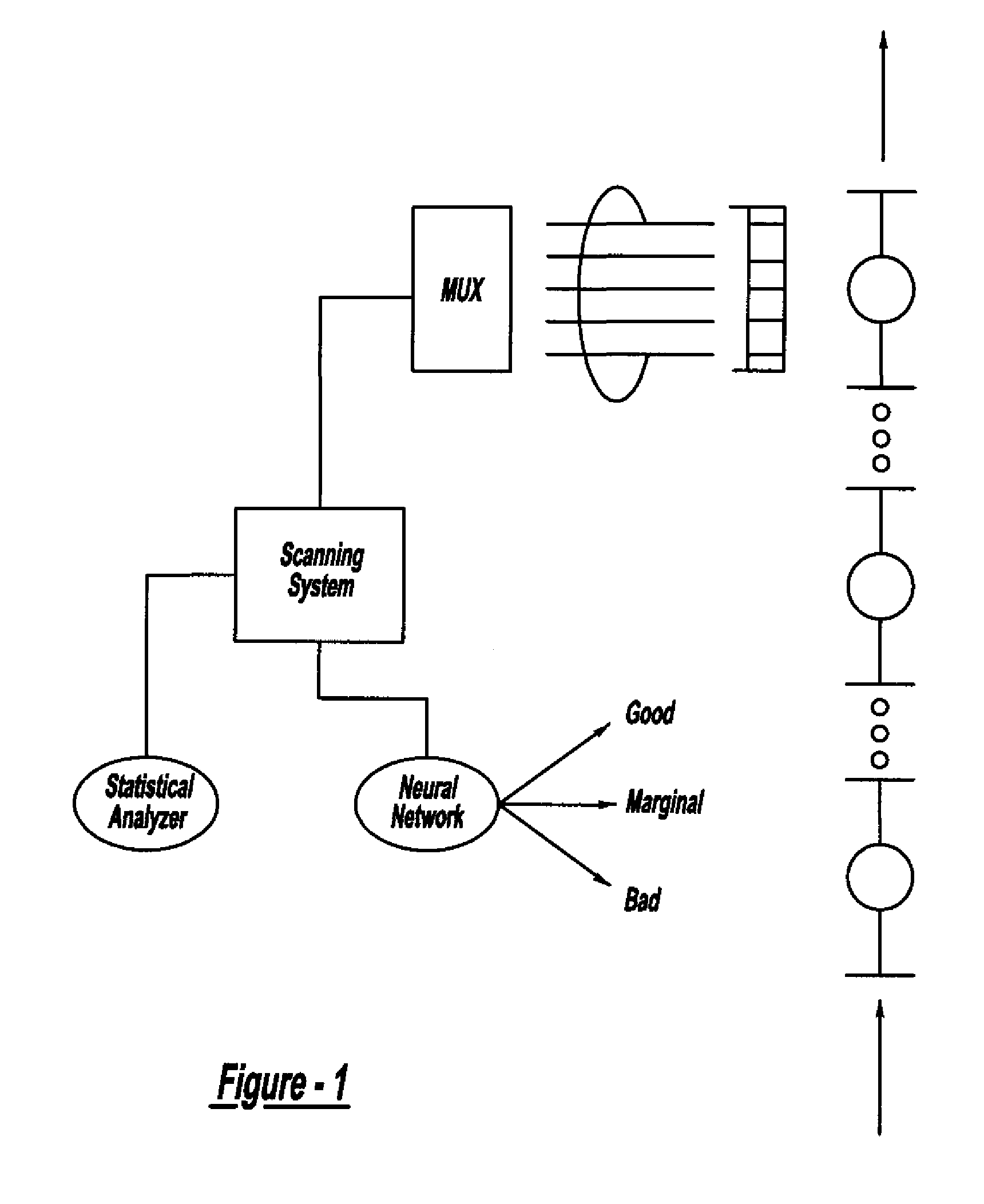
A system and method for assessing the quality of spot weld joints between pieces of metal includes an ultrasound transducer probing a spot weld joint. The ultrasound transducer transmits ultrasonic radiation into the spot weld joint, receives corresponding echoes, and transforms the echoes into electrical signals. An image reconstructor connected to the ultrasound transducer transforms the electrical signals into numerical data representing an ultrasound image. A neural network connected to the image reconstructor analyzes the numerical data and an output system presents information representing the quality of the spot weld joint. The system is trained to assess the quality of spot weld joints by scanning a spot weld joint with an ultrasound transducer to produce the data set representing the joint; then physically deconstructing the joint to assess the joint quality.

Description

CROSS-REFERENCE TO RELATED APPLICATIONS [0001] This application is a Divisional of U.S. patent application Ser. No. 10 / 370,540, filed Feb. 20, 2003, which claims the benefit of U.S. Provisional Patent Application Ser. No. 60 / 359,280 filed Feb. 20, 2002 and U.S. Provisional Patent Application Serial No. 60 / 1359,275, filed Feb. 20, 2002.FIELD OF THE INVENTION [0002] The present invention relates generally to a method and system for assessing the quality of spot welds and, more particularly, a non-destructive method and system for assessing the quality of spot welds according to measured acoustic parameters. BACKGROUND OF THE INVENTION [0003] Sheet metal joining processes are widely used in many industries, such as the aerospace and automotive industries. Among these processes, resistance spot welding is the most common procedure used to join metal sheets because it has high process speed and is easily adopted in mass production lines. As these industries grow, the quality control of s...

Claims


Application Information

Patent Timeline
Patent Type & Authority Applications(United States)
IPC IPC(8): G01N29/06G01N29/30B23K11/24B23K31/12G01N3/00G01N29/11G01N29/44
CPCB23K11/24B23K31/006B23K31/125G01N3/00G01N29/0681G01N29/11G01N2291/2672G01N2203/0051G01N2203/021G01N2203/0296G01N2291/02854G01N2291/02863G01N29/4481
Inventor LEE, HSU-TUNGMAEV, ROMAN GR.MAEVA, ELENA YUTITOV, SERGUEIA
Owner FCA US
Learn More