Electronic circuit unit having low transmission loss

a technology of electronic circuit unit and transmission loss, applied in the field of electronic circuit unit, can solve problems such as transmission loss, and achieve the effect of suppressing transmission loss and decreasing resistance valu

Inactive Publication Date: 2007-02-22
ALPS ALPINE CO LTD
View PDF2 Cites 2 Cited by
  • Summary
  • Abstract
  • Description
  • Claims
  • Application Information

AI Technical Summary

Benefits of technology

[0009] An object of the present invention is to provide an electronic circuit capable of decreasing a resistance value by equivalently increasing a thickness of a conductor pattern constituting a transmission line and suppressing a transmission loss due to a concentration of an electric field at a bend section even in the conductor pattern having a bend section.

Problems solved by technology

But, there is a problem that an electric field is concentrated on the bend section of the conductor pattern when high frequency current flows to the transmission line having such bend sections, thereby causing the transmission loss.

Method used


Image

  • Electronic circuit unit having low transmission loss
  • Electronic circuit unit having low transmission loss
  • Electronic circuit unit having low transmission loss

Examples


Embodiment Construction

[0030] Hereinafter, the embodiments of the present invention will be specifically described with reference to the accompanying drawings. A configuration of an electronic circuit unit according to the present embodiment is same as the circuit configuration shown in FIG. 6. That is, the electronic circuit unit has the configuration in which a matching circuit 101 is connected to an output end of a power amplifier 102 and an impedance matching is obtained between the power amplifier 102 and a load of a rear stage by a matching circuit.

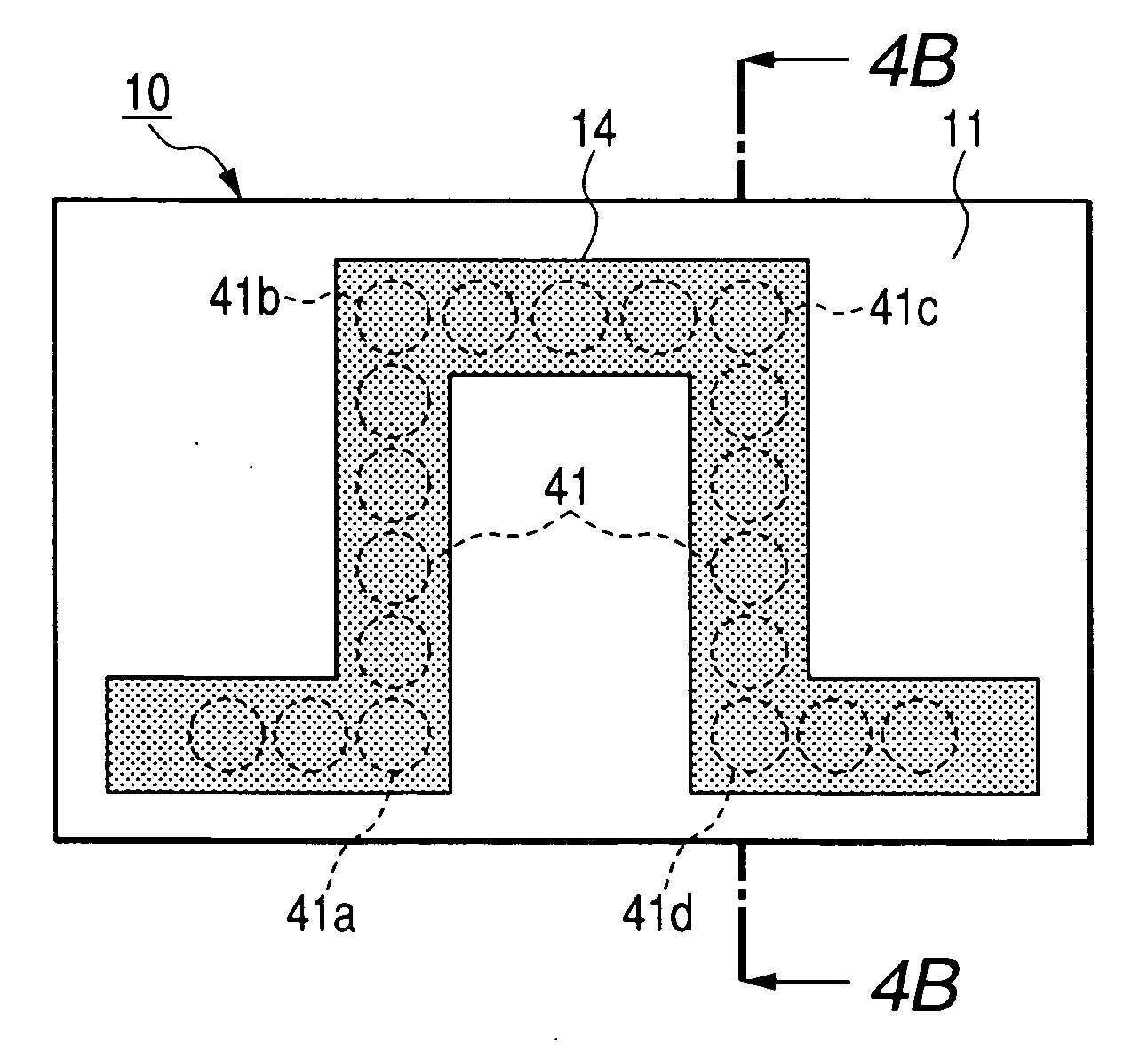
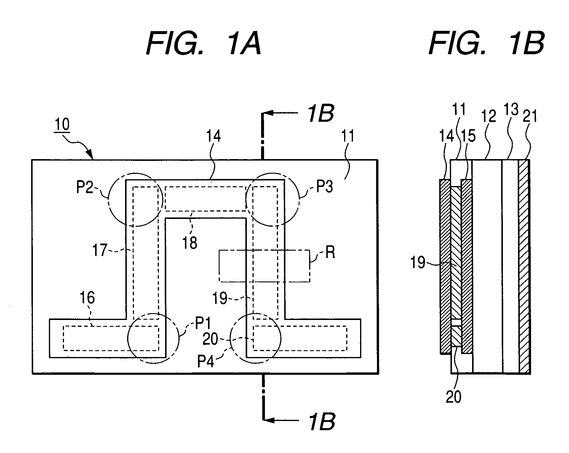
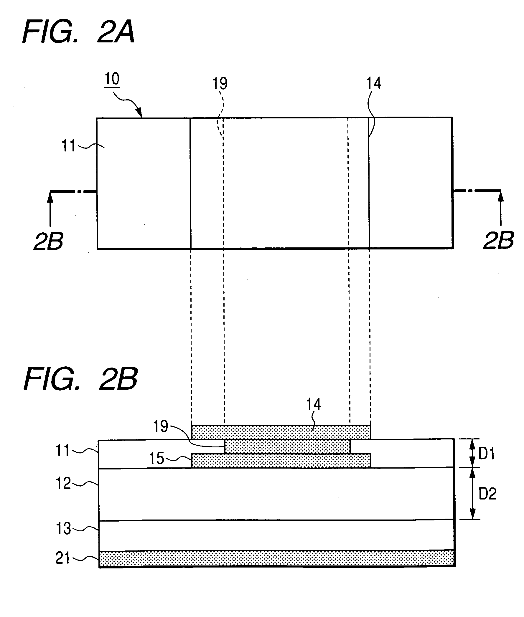
[0031]FIG. 1A and FIG. 1B are a plan view and a cross-sectional view of a transmission line in the electronic circuit unit according to an embodiment. As shown in FIGS. 1A and 1B, a laminated substrate 10 is constituted by a plurality of dielectric layers of a first dielectric layer 11, a second dielectric layer 12 and a third dielectric layer 13. A first conductor pattern 14 having a plurality of bend sections is formed on a surface of the first dielect...


PUM


Abstract

In an electronic circuit unit for transmitting power through a transmission line 103 formed of a conductor pattern, a matching circuit 101 is connected to an output end of a power amplifier 102. The matching circuit 101 comprises a first conductor pattern 14 having bend portions P1 to P4 provided on a first dielectric substrate 11 of a laminated substrate 10 which has a plurality of dielectric layers 11 to 13, and a second conductor pattern 15 disposed opposite the first conductor pattern 14 on an adjacent second dielectric layer 12, and connecting conductors 16 to 20 provided at at least bend portions P1 to P4 of the first and second conductor patterns.

Description

FIELD OF THE INVENTION [0001] The present invention relates to an electronic circuit unit having a transmission line for transmitting a high-frequency signal. DESCRIPTION OF THE RELATED ART [0002] Conventionally, in a high frequency circuit, an impedance matching is performed between circuits by a matching circuit so as to transmit power without loss. [0003]FIG. 6 is shows a matching circuit disposed at an output stage of a power amplifier. Since the matching circuit 101 is disposed at an output end of the power amplifier 102, an output of the power amplifier 102 is transmitted to a load of a rear stage through a transmission line 103 of the matching circuit 101. A parallel resonance circuit consisting of a power feeding line 105 grounded through a by-pass capacitor 104 and an output capacitor 106 is connected to a collector of a transistor 107. Meanwhile, one capacitor 118 is serially connected to an output side of the transmission line 103, and the other capacitor 119 is parallell...

Claims


Application Information

Patent Timeline
Patent Type & Authority Applications(United States)
IPC IPC(8): H03H7/38
CPCH01P5/02H03F3/60H03F2200/423H05K1/0237H05K1/0265H05K3/4644H05K2201/09672H05K2201/0979
Inventor AOKI, KAZUHARU
Owner ALPS ALPINE CO LTD
Why Eureka
Try Eureka