Radar device

a technology of radar and detector, applied in the direction of measurement devices, instruments, using reradiation, etc., can solve the problem that the dirty detection process cannot be executed, and achieve the effect of reliably and quickly

Active Publication Date: 2007-02-22
MITSUBISHI ELECTRIC CORP
View PDF21 Cites 15 Cited by
  • Summary
  • Abstract
  • Description
  • Claims
  • Application Information

AI Technical Summary

Benefits of technology

[0014] The present invention provides a radar device, including: transmitting means for transmitting an electric wave as a transmission signal; receiving means for receiving a reflected wave resulting from reflecting the transmission signal from an object as a reception signal; detecting means which mixes the transmission signal and the reception signal together to generate a beat signal for detecting the object according to the beat signal; measuring means for measuring a distance to the object and a relative speed of the object on the basis of the beat signal; unmodulated pulse transmitting means for modulating

Problems solved by technology

However, in the case where a change in the level of the low frequency component is detected in the FM system, because a signal from the object is superimposed on t

Method used


Image

  • Radar device
  • Radar device
  • Radar device

Examples


first embodiment

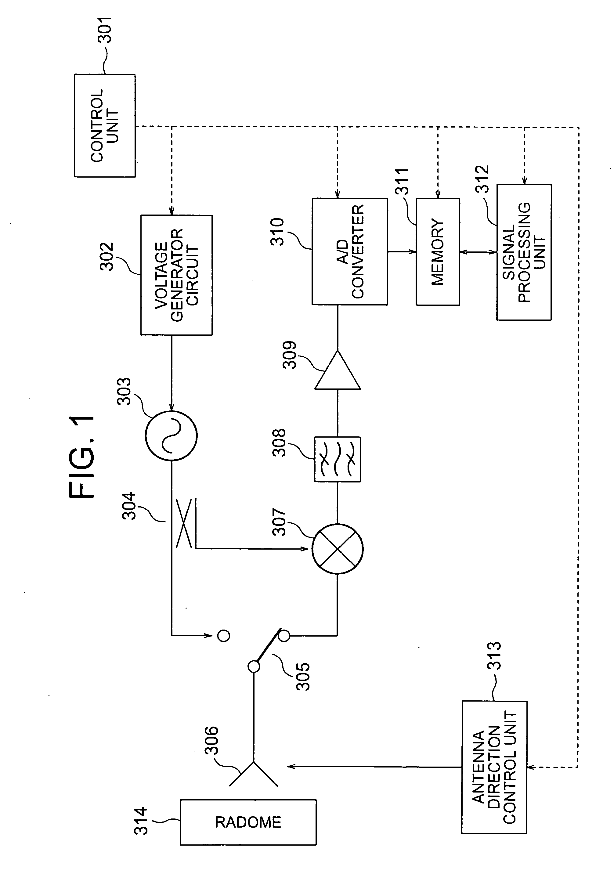
[0030]FIG. 1 is a structural diagram showing a structure of an in-vehicle radar device in accordance with a first embodiment of the present invention. As shown in FIG. 1, the in-vehicle radar device according to the first embodiment is constructed of a control unit 301, a voltage generator circuit 302 that generates a modulation signal, a voltage control oscillator (hereinafter referred to as “VCO”) 303, a distributor 304, a transmit / receive changeover switch 305, a transmit / receive shared antenna 306, and a mixer 307. The in-vehicle radar device is also constructed of a band pass filter (BPF) 308, an amplifier 309, an analog to digital (hereinafter referred to as “A / D”) converter 310, a memory 311, a signal processing unit 312, and an antenna direction control unit 313. Hereinafter, the respective structural elements will be described. Note that, in FIG. 1, solid lines indicate electric connections and broken lines indicate transmission of a control signal.

[0031] The control unit ...

second embodiment

[0067] A description will be given as to an in-vehicle radar device according to a second embodiment of the present invention. The structure of the in-vehicle radar device according to this embodiment is basically identical with that in FIG. 1, and therefore FIG. 1 is referred to and its description will be omitted.

[0068] Hereinbelow, the transmitting operation will be described.

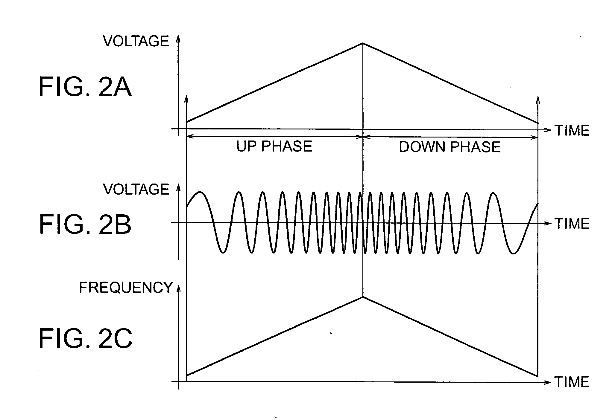
[0069] First, the voltage generator circuit 302 that is controlled in timing by the control unit 301 generates a voltage shown in FIG. 9A which temporally changes from a chopping wave shape into a constant voltage, and applies the voltage to the VCO 303. The VCO 303 generates a frequency modulated continuous wave (FMCW) that temporally changes the frequency and an unmodulated continuous wave according to the applied voltage, and then outputs the FMCW to the distributor 304. In terms of those continuous waves, a voltage change with respect to time is shown in FIG. 9B, and a frequency change with respect to ...


PUM


Abstract

A radar device can reliably, and rapidly detect dirt adhered to a radome surface without misdetection. The radar device includes a transmit/receive shared antenna (306) that transmits an electric wave to an object and receives a reflected wave that has been reflected from the object, a mixer (307) that mixes a transmission signal and a reception signal together to generate a beat signal, and a signal processing unit (312) that measures a distance to the object and a relative speed of the object on the basis of the beat signal. The transmit/receive shared antenna (306) modulates an unmodulated wave into a pulse and transmits the pulse modulated wave at a specific timing. In the case where the unmodulated pulse is transmitted, the beat signal that has been generated by the mixer (307) is converted into a digital voltage value by an A/D converter (310). The signal processing unit (312) detects the dirt that is adhered to the radome (314) of the transmit/receive shared antenna (306) on the basis of an output of the A/D converter 310.

Description

BACKGROUND OF THE INVENTION [0001] 1. Field of the Invention [0002] The present invention relates to a radar device, and more particularly to a radar device that can detect not only an object but also dirt that is adhered to a radome of an antenna on the basis of a reflected signal. [0003] 2. Description of the Related Art [0004] As a conventional radar device, there has been proposed an FM radar device that extracts a low frequency component of a beat signal by a low pass filter, performs the extracted low frequency component to A / D conversion by an A / D converter, performs fast Fourier transformation by a fast Fourier transformer, and compares frequency spectrum data, in which a low frequency component in a state where no dirt is adhered to a radome is stored, with inputted frequency spectrum data of a low frequency component to detect that dirt is adhered to the radome (for example, refer to JP 10-282229A). [0005] Also, as another conventional radar device, there has been proposed...

Claims


Application Information

Patent Timeline
IPC IPC(8): G01S13/42
CPCG01S7/4004G01S13/34G01S13/36G01S2007/4039G01S7/4039
Inventor MATSUOKA, KATSUJI
Owner MITSUBISHI ELECTRIC CORP
Why Eureka
Try Eureka