
Laser-scribed grain-oriented silicon steel resistant to stress-relief annealing and manufacturing method therefor

a grain-oriented silicon and stress-relief technology, applied in the field of grain-oriented silicon steel, can solve the problems of etching technique that is not resistant, method can only be used in the manufacture of laminated iron core transformers without stress-relief, and steel has a reactive power consumption that accounts for about 20% of the total loss under working conditions, so as to reduce iron loss, reduce iron loss, and reduce the iron loss of silicon steel sheets.

Active Publication Date: 2020-02-20
BAOSHAN IRON & STEEL CO LTD
View PDF0 Cites 3 Cited by
  • Summary
  • Abstract
  • Description
  • Claims
  • Application Information

AI Technical Summary

Benefits of technology

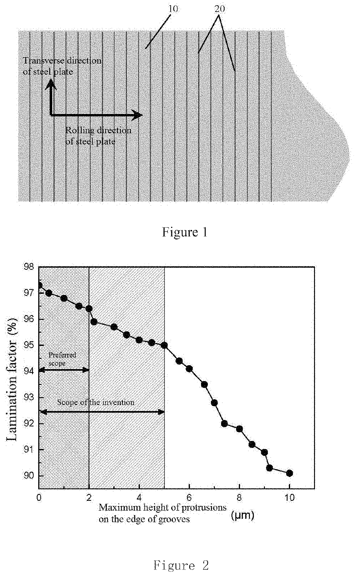
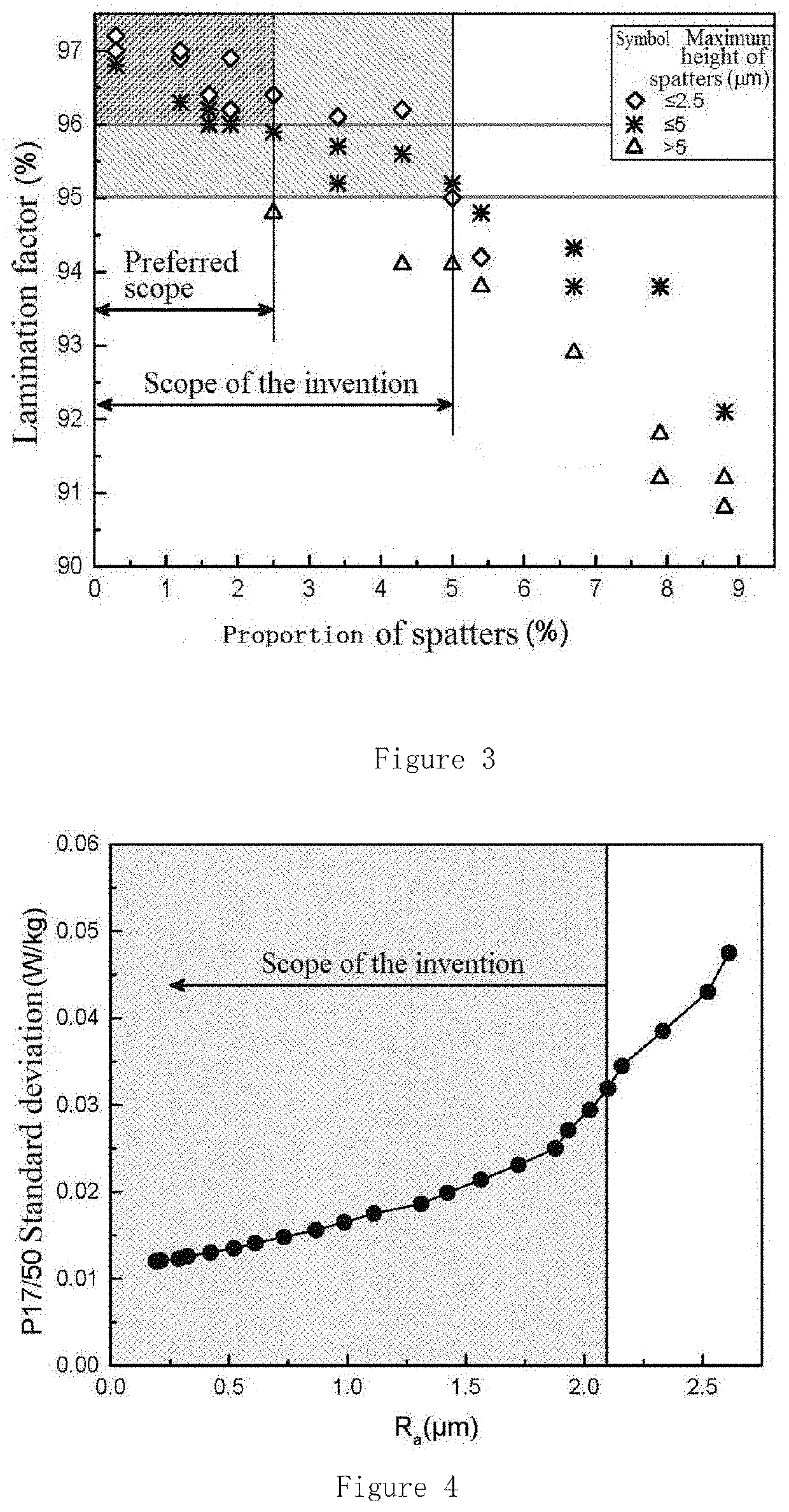
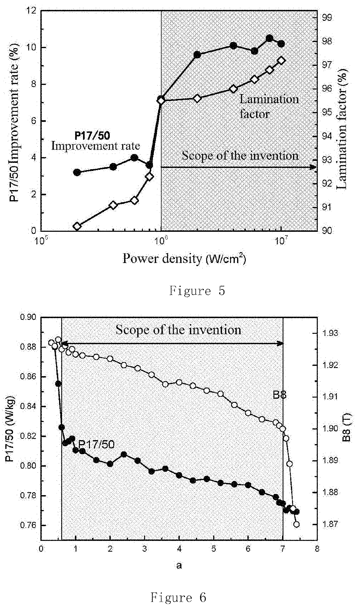
The present invention relates to a method for improving the magnetic properties of grain-oriented silicon steel by etching the surface with a laser. The technical solution is achieved by controlling the ratio between the energy density of the laser and the thickness of the film on the surface. By optimizing the etching effect, the inventors found that a ratio of 0.6 to 7.0 is ideal for achieving the desired magnetic properties. The patent also discusses the effects of etching grooves and scoring lines on the magnetic domain and iron loss. The optimal conditions for grooves are a width between 5 and 300 μm, a depth between 5 and 60 μm, and a space between adjacent grooves between 1 and 10 mm. The method uses a protective film and a heat-resistant laser-etching process. The patent describes the various shapes and arrangements of the grooves and scoring lines that can be used to achieve the desired magnetic properties.

Problems solved by technology

The iron core produced by laminating or winding grain-oriented silicon steel has a reactive power consumption that accounts for about 20% of the total loss under working conditions.
One type is an etching technique that is not resistant to stress-relief annealing.
Therefore, such method can only be used in the manufacture of laminated iron core transformers without stress-relief annealing.
The iron loss of the grain-oriented silicon steel produced by such a method does not recover after stress-relief annealing.
Efficient and low-cost production of the grain-oriented silicon steel resistant to stress-relief annealing is a common problem for steel manufacturers.
The key point thereof is that it is difficult to obtain both the microscopic characteristics of the etching grooves and macro mass production.
The conventional heat-resistant etching technique by electrochemical means has a complicated process and a certain degree of chemical contamination.
Moreover, the shape and depth of the grooves are less controllable, and it is difficult to obtain a grain-oriented silicon steel sheet having stable and uniform magnetic properties.
The technical solution of forming grooves by mechanical pressure is extremely demanding on the toothed rolls.
Moreover, the high hardness of the magnesium silicate underlayer on the surface of the grain-oriented silicon steel causes the toothed rolls to wear quickly, resulting in high cost in mass production.
The method of forming grooves by multiple laser-scanning requires high repeat positioning precision, resulting in difficulty in flow line production.
The method of forming grooves or remelting zones by laser thermal melting tends to produce crater-like protrusions and spatters at and near the edge of the grooves, resulting in a decrease in the lamination factor of the silicon steel sheets.
And the transformer made by the method has the risk of breakover between sheets during the service.
However, internal stress generated in the iron core during the winding process causes deterioration of the iron loss performance of the silicon steel plate.
Therefore, such grain-oriented silicon steel plate cannot be used for the manufacture of a wound iron core transformer.
Since the production process of the chemical etching method involves chemical reactions, the method has proor groove uniformity and process controllability, and has certain pollution to the environment.
Due to the high melting point and high thermal conductivity of the metal, crater-like protrusions are formed at the edges of the grooves due to the melting of the metal, and adhesive deposits formed by cooling and recondensing after the metal gasification will be produced in the vicinity, reducing the lamination factor of the silicon steel sheet and increasing the risk of breakover between the sheets during the service of the transformer.
However, the efficiency of repeated scoring is low, and repeated positioning is difficult, resulting in difficulty in mass production using industrial assembly lines.

Method used


Image

  • Laser-scribed grain-oriented silicon steel resistant to stress-relief annealing and manufacturing method therefor
  • Laser-scribed grain-oriented silicon steel resistant to stress-relief annealing and manufacturing method therefor
  • Laser-scribed grain-oriented silicon steel resistant to stress-relief annealing and manufacturing method therefor

Examples


example 1

[0075]The grain-oriented silicon steel was subjected to iron making, steel making, continuous casting, and hot rolling process. Next, single cold rolling was performed to roll the steel to a final thickness of 0.23 mm. Then, decarburization annealing was performed to form a surface oxide layer. Then, the steel was coated with MgO separator on the surface, and subjected to high-temperature annealing at 1250° C. for 20 hours. Then, unreacted residual MgO was washed away. Thereafter, the surface of the steel was roll coated and dried to form a protective film. Next, a YAG laser was used to etch linear grooves at equal intervals along the rolling direction of the steel plate. The laser has an output power of 2000 W and an average pulse width of 800 ns. The spot formed by the laser focusing on the surface of the steel plate was elliptical with a short axis of 0.016 mm and a long axis of 0.5 mm. The scanning speed is 50 m / s. The calculated laser power density was 3.2×10⁷ W / cm2, and the la...

example 3

[0081]The grain-oriented silicon steel was subjected to iron making, steel making, continuous casting, and hot rolling process. Next, single cold rolling was performed to roll the steel to a final thickness of 0.225 mm. An Al2O3 protective film was applied by spraying on the surface of the steel. The proportion of Al2O3 particles having a particle diameter of 500 μm or more in the protective film is about 5%. Then, a YAG laser having a pulse width of 300 ns was used to etch linear grooves. Approximate triangular grooves were formed by adjusting the size of the focused spot, the scanning speed, and the laser scoring energy. The angle between scoring lines and the transverse direction of the steel plate is 8°, and the space between scoring lines in the rolling direction is 4 mm. Then, a brushing process was performed to remove the surface protective film. Then, decarburization annealing was performed to form a surface oxide layer. Then, the steel was coated with MgO separator on the s...

example 4

[0084]The grain-oriented silicon steel was subjected to iron making, steel making, continuous casting, and hot rolling process. Next, single cold rolling was performed to roll the steel to a final thickness of 0.195 mm. Then, decarburization annealing was performed to form a surface oxide layer. Then, the steel was coated with MgO separator on the surface to obtain a film having a thickness of about 9.5 μm. Next, a YAG laser was used to etch linear grooves at equal intervals along the rolling direction of the steel plate. The laser has an output power of 2000 W and an average width of a single pulse of 800 ns. The spot formed by the laser focusing on the surface of the steel plate was elliptical with a short axis of 0.016 mm and a long axis of 0.5 mm. The scanning speed is 50 m / s. The calculated laser power density was 3.2×10⁷ W / cm2, and the laser energy density was 3.2 J / mm2. The formed scoring lines are perpendicular to the rolling direction of the steel plate. The space between a...


PUM

PropertyMeasurementUnit
Fractionaaaaaaaaaa
Fractionaaaaaaaaaa
Thicknessaaaaaaaaaa

Abstract

A laser-scribed grain-oriented silicon steel resistant to stress-relief annealing and a manufacturing method therefor. Parallel linear grooves (20) are formed on one or both sides of grain-oriented silicon steel (10) by laser etching. The linear grooves (20) are perpendicular to, or at an angle to, the rolling direction of the steel plate. A maximum height of edge protrusions of the linear grooves (20) does not exceed 5 μm, and a maximum height of spatters in etch-free regions between adjacent linear grooves (20) does not exceed 5 μm, and the proportion of an area occupied by spatters in the vicinity of the linear grooves (20) does not exceed 5%. The steel has low manufacturing costs, and the etching effect of the finished steel is retained during a stress-relief annealing process. The steel is suitable for manufacturing of wound iron core transformers.

Description

TECHNICAL FIELD[0001]The present invention relates to grain-oriented silicon steel and a manufacturing method therefor, and particularly to laser-scribed grain-oriented silicon steel resistant to stress-relief annealing and a manufacturing method thereforBACKGROUND ART[0002]In recent years, global energy and environmental issues have become increasingly prominent, and the demand for energy conservation and consumption reduction is increasing worldwide. As a result, energy consumption standards of equipment have been generally raised in countries in order to reduce the reactive power consumption of various types of equipment. At present, transformers, as a basic component of power transmission systems, account for about 40% of the loss of the power transmission system. The iron core produced by laminating or winding grain-oriented silicon steel has a reactive power consumption that accounts for about 20% of the total loss under working conditions. Iron core loss is often referred to ...

Claims


Application Information

Patent Timeline
IPC IPC(8): H01F27/245B23K26/364C21D8/12C25F3/06
CPCC21D8/1283H01F27/245C25F3/06C21D8/1294B23K26/364C21D8/1222C21D8/1233C21D8/1266C21D8/1277C21D8/12
Inventor ZHAO, ZIPENGLI, GUOBAOYANG, YONGJIEWU, MEIHONGMA, CHANGSONGJI, YAMINGLING, CHENXIE, WEIYONGGUO, JIANGUO
Owner BAOSHAN IRON & STEEL CO LTD
Learn More