Frequency changer and tuner

a frequency changer and tuner technology, applied in the field of frequency changers and tuners, can solve the problems of inability to achieve acceptable reception, inability and inability to use intermediate frequency or subsequent filtering to remove interfering signals or nois

a frequency changer and tuner technology, applied in the field of frequency changers and tuners, can solve the problems of inability to achieve acceptable reception, inability and inability to use intermediate frequency or subsequent filtering to remove interfering signals or nois

US20070042743A1Inactive Publication Date: 2007-02-22INTEL CORP

Image

  • Frequency changer and tuner
  • Frequency changer and tuner
  • Frequency changer and tuner

Examples


Embodiment Construction

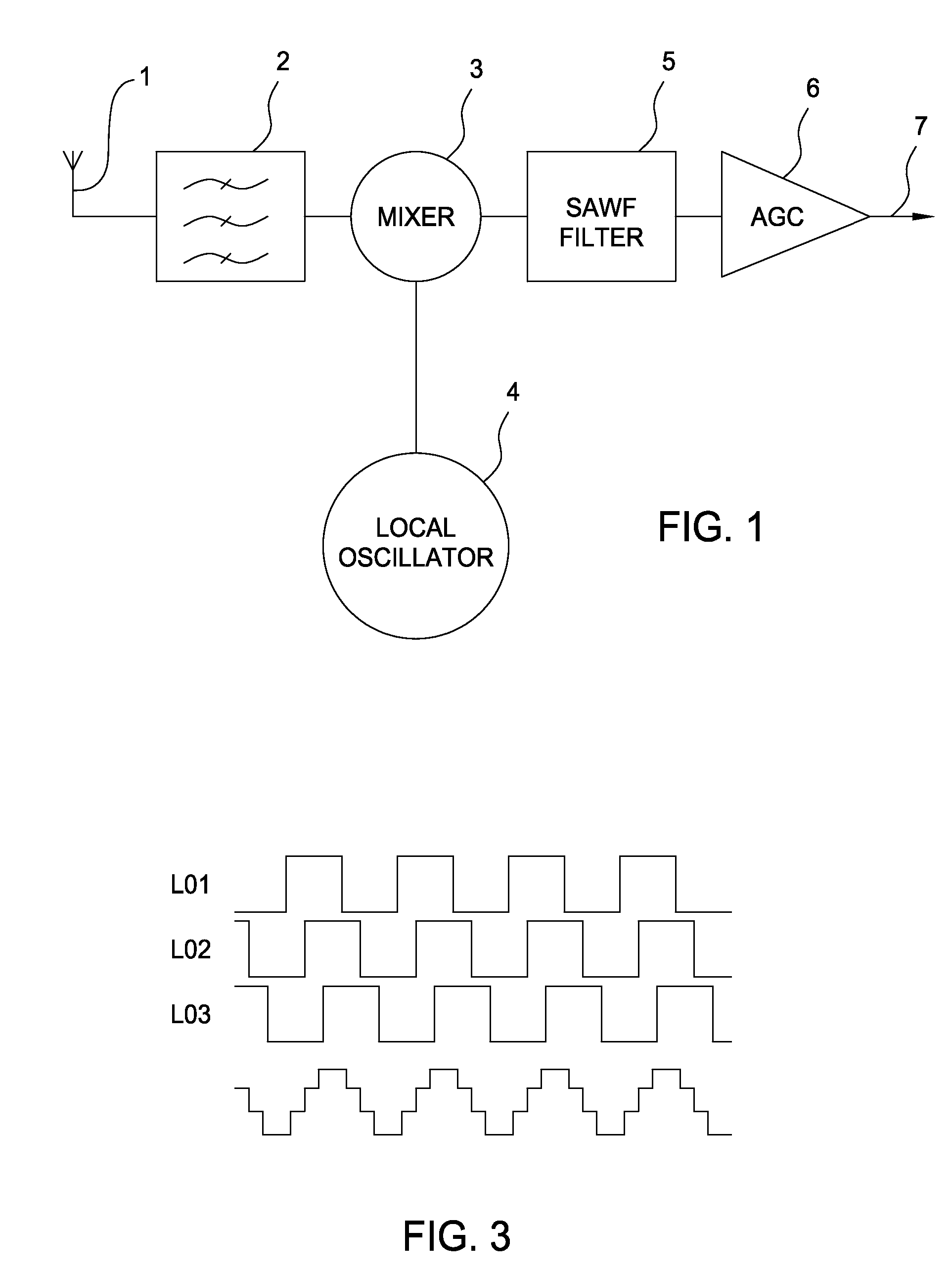
[0030] The tuner shown in FIG. 1 may be used for receiving digitally or analogically encoded signals from any distribution or broadcast medium. Examples of such media are terrestrial broadcast, satellite broadcast and cable distribution. The signals may represent any or any combination, of television, audio, telephony and data. The tuner may be of the “classical” intermediate frequency (IF) type in which any of the channels received in a broadband input signal can be selected for reception and be converted to a conventional intermediate frequency, for example, between 30 and 50 MHz. The illustrated tuner is thus of the single conversion type. However, the arrangement illustrated in FIG. 1 may form part of a dual conversion tuner. For example, this arrangement may act as a first upconverter for converting the selected desired channel to a relatively high first intermediate frequency. In the case where the spectrum of the input signal is from 50 to 860 MHz, the first intermediate freq...


PUM


Abstract

A frequency changer for a radio frequency tuner and a tuner incorporating such a frequency changer are provided. The frequency changer comprises a mixer comprising a plurality of mixing stages. The output signals of these stages are supplied without relative phase shift to a summer, for example, in the form of a common load arrangement. The inputs of the stages are connected together to form a signal input of the mixer. Commutating signal inputs of the mixing stages received from the local oscillator are of the same frequency, but of different phases. The commutating signals are square or rectangular waves.

Description

CROSS-REFERENCE TO RELATED APPLICATION [0001] This application claims priority to British Patent Application Serial Number GB 0516766.3, filed Aug. 16, 2005, which is herein incorporated by reference. BACKGROUND OF THE INVENTION [0002] 1. Field of the Invention [0003] Embodiments of the present invention relate to a frequency changer for a radio frequency tuner and to a tuner including such a frequency changer. Such a tuner may be used, for example, for receiving digital or analog broadcast signals from a terrestrial aerial, a satellite aerial system or a cable distribution system. Such a tuner may be used, for example, for receiving digital television signals, digital audio broadcast signals, telephony or data signals. [0004] 2. Description of the Related Art [0005] Known types of radio frequency tuners comprise one or more frequency changers for converting a desired channel from a broadband input spectrum to a predetermined intermediate frequency. A typical broadband spectrum comp...

Claims


Application Information

Patent Timeline
22 Feb 2007
Publication
US20070042743A1
IPC
H04B1/26; H03D7/16; H03K5/15; H03K23/54
CPC
H03D7/165; H03D7/166; H03K5/15093; H03K23/542; H04B1/26
Inventors
ALI, ISAAC; COWLEY, NICHOLAS PAUL