Systems and methods for monitoring thermal growth and controlling clearances, and maintaining health of turbo machinery applications

a technology of thermal growth monitoring and control clearance, which is applied in the direction of machines/engines, using reradiation, instruments, etc., can solve the problems of long knowledge and control of radial growth of turbo-machinery components, undesirable situation, lack of reliable, accurate and affordable sensors

Active Publication Date: 2007-02-22
RAYTHEON TECH CORP
View PDF7 Cites 55 Cited by
  • Summary
  • Abstract
  • Description
  • Claims
  • Application Information

AI Technical Summary

Benefits of technology

[0009] In accordance with the present systems and methods disclosed herein, a method of controlling clearance in a turbomachine broadly comprises providing a closed loop sensed active clearance control system comprising three or more microwave-based sensors disposed adjacent to and opposing one or more components and sub-components of the turbomachine; determining from a measurement an actual amount of thermal growth on one or more components and the sub-components using the active clearance control system; determining from a

Problems solved by technology

The knowledge and control of radial growth of turbo-machinery components has long been a stumbling block on the way to achieving higher efficiency and stability levels demanded by the designers of gas turbine engines, pumps and compressors.
This undesirable situation is driven in part by lack of reliable, accurate and affordable sensors for measuring radial growth.
However, none of the known algorithms delivered required steady state and transient accuracy, ability to calibrate the equations to high fidelity data and formulation suitable for implementation in a digital computer.
Imperfect control of the clearance between a turbine engine fan blade and case can result in either the clearance being too loose or the clearance being too tight resulting in excessive rubs.
In either instance, imperfect clearance results in loss of performance (e.g. engine efficiency, thrust) and/or violation of the engine operating limits (e.g. exhaust gas temperature overshoot) and/or reduced compressor stability.
Standard practice has been to design a clearance control system to prefer loose clearance over tight clearance which may also result in damage to the blades and case.
Some engines such as, for example, the PW4000 use an open loop clearance control system that sacrifices significant performance in comparison with a “perfect” clearance control system.
Other engines such as, for examp

Method used


Image

  • Systems and methods for monitoring thermal growth and controlling clearances, and maintaining health of turbo machinery applications
  • Systems and methods for monitoring thermal growth and controlling clearances, and maintaining health of turbo machinery applications
  • Systems and methods for monitoring thermal growth and controlling clearances, and maintaining health of turbo machinery applications

Examples


Embodiment Construction

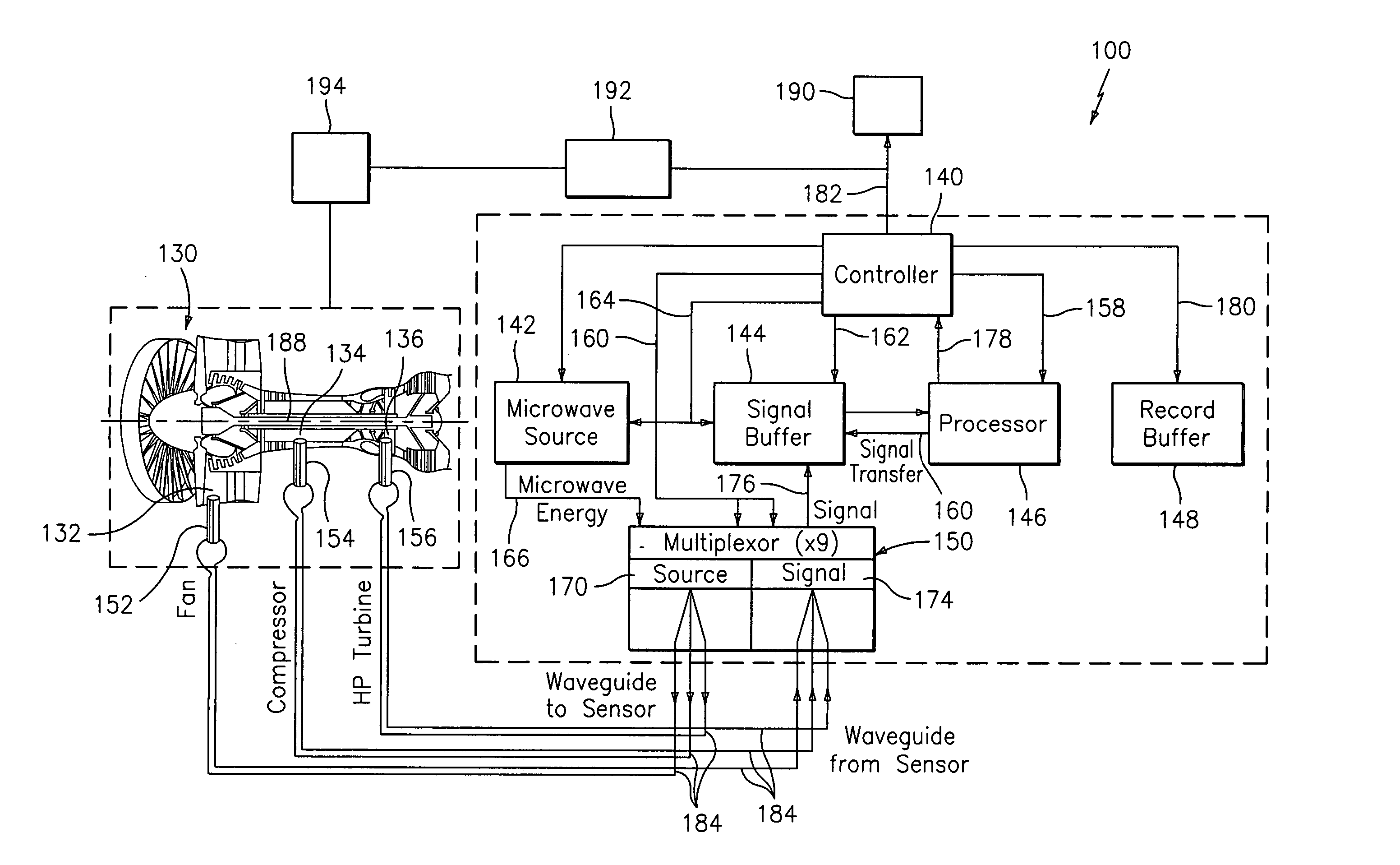
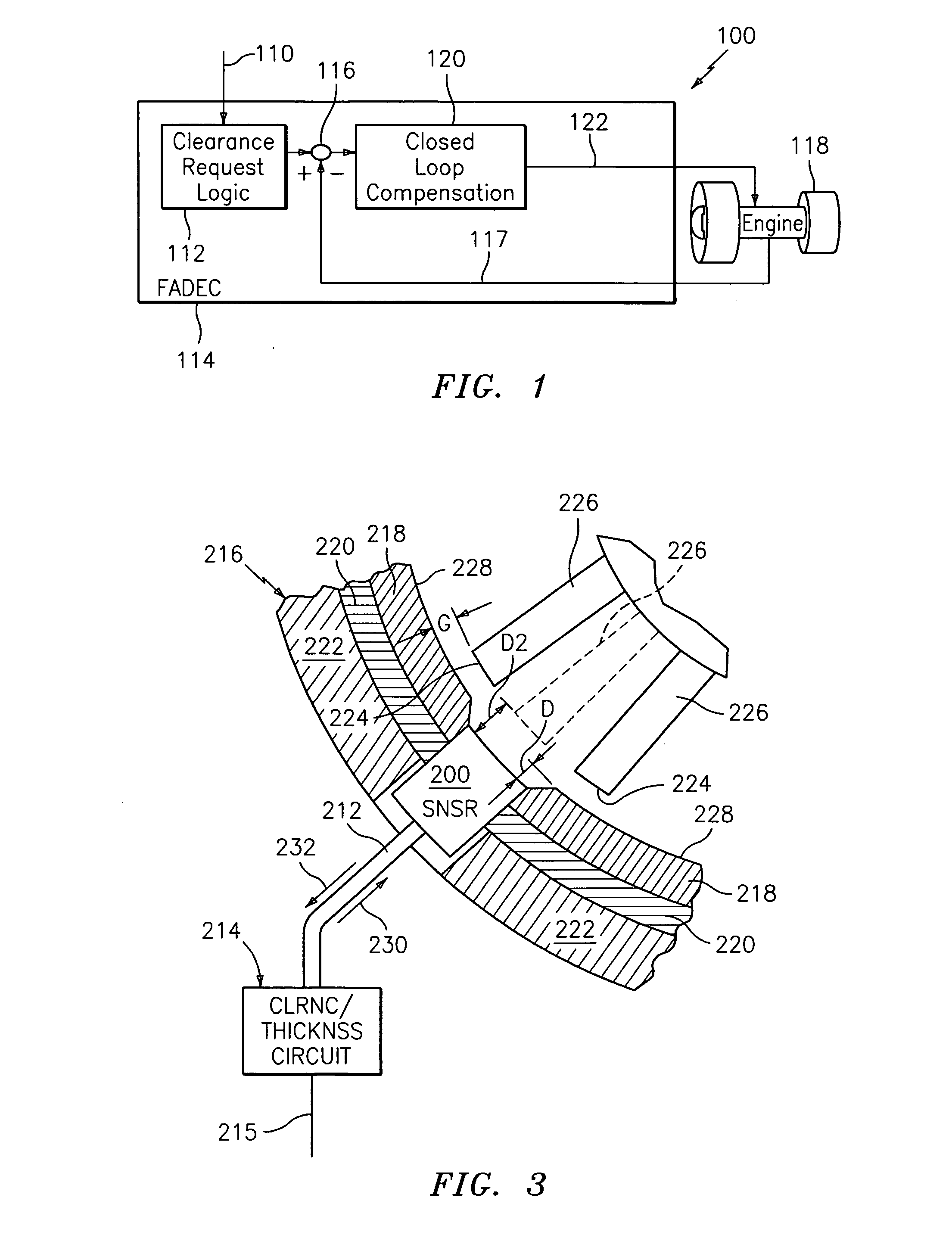
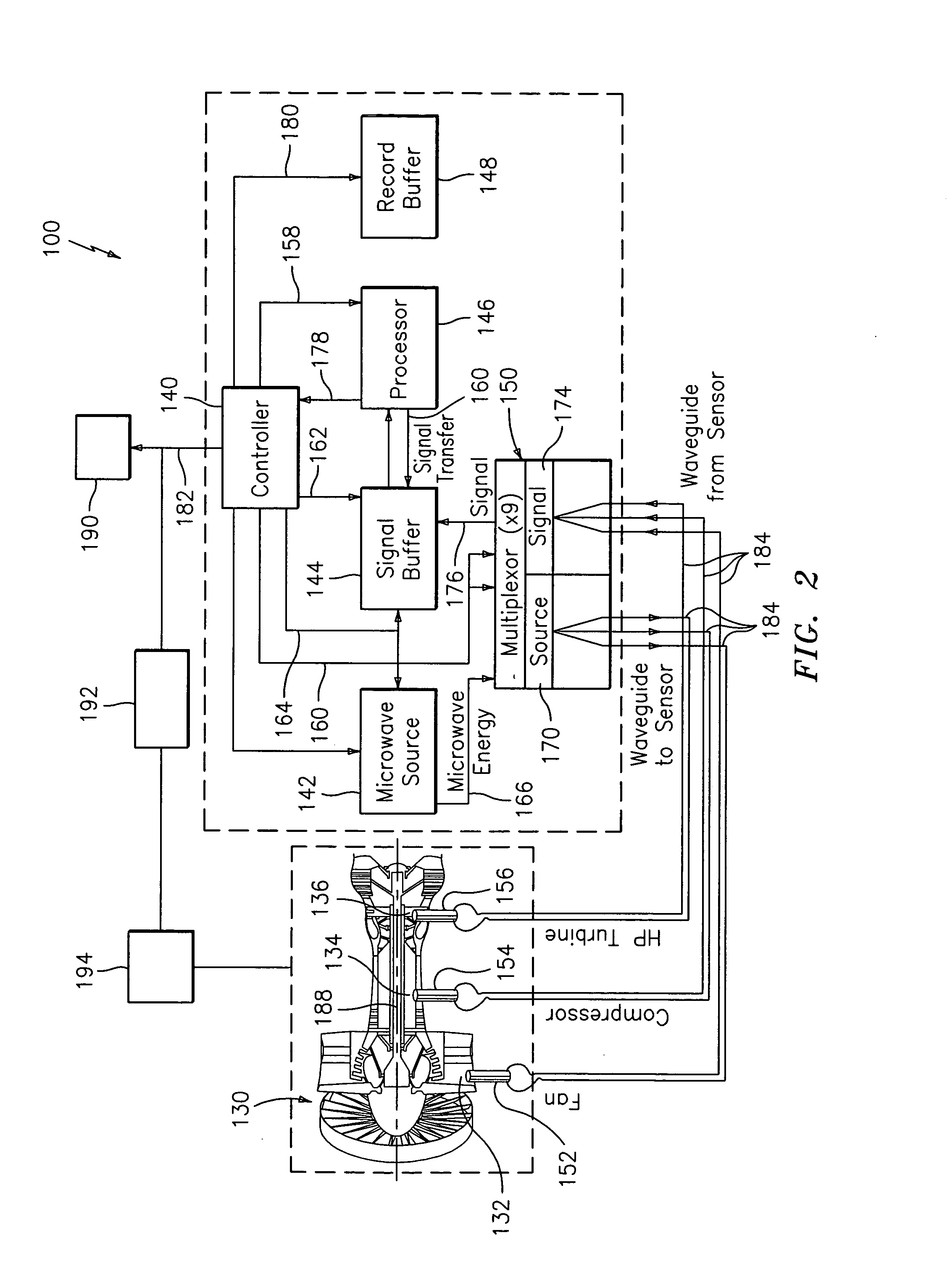
[0021] A system and method for determining thermal growth of motor or engine parts to thereupon control the clearance of motor or engine fan blades is disclosed herein. In addition, a system and method for monitoring the health of a turbine engine, its components and sub-components is also described herein. Increasing radial clearances caused by the blade tips rubbing into the outer airseals and / or erosion are common root causes of a loss of engine performance. Early detection of problems with turbo machine blades and / or rotors enables avoidance of component failures. The system(s) and method(s) described herein permit continuous monitoring during the life of the engine for radial clearances and blade and rotor vibration problems, which will assist in correcting and retaining performance for a longer on-wing time in operation. In addition, inconsistent engine-to-engine performance variations due to component tolerances, engine operation characteristics, and operation during extremes...


PUM


Abstract

A system and method for determining thermal growth of motor or engine parts to thereupon control the clearance of motor or engine fan blades is disclosed herein. In addition, a system and method for monitoring the health of a turbine engine, its components and sub-components is also described herein. The system(s) and method(s) described herein permit continuous monitoring during the life of the engine for radial clearances and blade and rotor vibration problems, which will assist in correcting and retaining performance for a longer on-wing time in operation. In addition, inconsistent engine-to-engine performance variations due to component tolerances, engine operation characteristics, and operation during extremes in ambient temperatures can be eliminated or significantly minimized when employing the system(s) and method(s) described herein.

Description

GOVERNMENT INTERESTS [0001] The U.S. Government has certain rights in this application pursuant to Contract No. F33615-98-C-28012 awarded by the Department of the Air Force.FIELD OF THE INVENTION [0002] The present invention generally relates to a system and method of clearance control of motor or engine fan blades, and more particularly relates to a system and method of determining thermal growth of motor or engine parts to thereupon control the clearance of motor or engine fan blades. BACKGROUND OF THE INVENTION [0003] The knowledge and control of radial growth of turbo-machinery components has long been a stumbling block on the way to achieving higher efficiency and stability levels demanded by the designers of gas turbine engines, pumps and compressors. This undesirable situation is driven in part by lack of reliable, accurate and affordable sensors for measuring radial growth. Alternatively, the radial growth can be computed using a mathematical model that relates growth to var...

Claims


Application Information

Patent Timeline
IPC IPC(8): G06F19/00
CPCF01D11/24F01D21/003F01D21/04G01B15/06F05D2270/304F05D2270/305F05D2220/36G01B7/14G01S13/88
Inventor LEOGRANDE, JOHN A.JALBERT, PETER L.WOOD, C. BRUCESCHRYVER, MATTHEW J.
Owner RAYTHEON TECH CORP
Why Eureka
Try Eureka